Noise Figure
Introduction
Previously, we looked at environmental factors such as distance, obstructions, Fresnel zones etc. that contributed to signal loss during propagation (see propagation article). The final signal that arrives at the receiving antenna will depend on transmission power, propagation losses and gain of transmit/receive antennas (see article on link budget for more details) which is then measured against the receiver sensitivity.
However in practice there will be noise that will impact the receiver. While mainly referring to external sources, another source of noise is the receiver itself or more specifically, its internal components. This article aims to cover this in detail.
Noise floor
Noise at the receiver is commonly referred to as the receiver noise floor. There are many sources of unwanted signals which add up along the entire communication chain and so noise is continuous across all frequencies. For signals to be discernable, the signal levels must be higher than this noise level.
For this article we will consider 2 sources not from the environment that contribute to the noise floor:
- Thermal noise. This is thermal noise* due to thermal agitation of electrons in electrical conductors.
- Receiver noise. Components that make up e.g. amplifiers, mixers in the receiver are all individual sources which further increase the total noise floor at the output. This is the Noise Figure or (NF).
* Commonly referred to as \(k\times{T}\times{B}\) where k is Boltzmann's constant, T is temperature in K and B is bandwidth in Hz. As shorthand it can be expressed in per unit Hz as -174 dBm / Hz at 300K (room temperature). We can relate this to other bandwidths i.e. a doubling of bandwidth will add 3 dB to the current value and ten times will add 10 dB and so on.
Below are some examples for thermal noise at a temperature of 300K:
| Signal bandwidth | Thermal noise | Notes |
|---|---|---|
| 1 Hz | -174 dBm | For a signal of 1 Hz bandwidth. |
| 10 Hz | -164 dBm | |
| 12 kHz | -133 dBm | Narrowband module for example, STD-302Z |
| 200 kHz | -121 dBm | FM broadcast channel |
| 6 MHz | -106 dBm | Analogue television channel |
You may have heard of the terms "narrowband" and "wideband". In narrowband, we limit data rates in order to confine our signal to a narrower range of frequencies and you can see why from above. When bandwidth is decreased, so does the noise which improves coverage. This is useful in applications such as periodic acquisition of sensor data which do not require high data rates.
Receiving level for communication
We can therefore determine the minimum receiving level that factors in thermal noise, total noise figure and minimum required SNR (signal to noise ratio).

The noise floor due to the thermal noise and noise figure. Additional noise from the environment would increase the noise floor further.
$$\text {Minimum receive level (dBm)} = 10\log(kTB(W)) + 30 + NF(dB) + SNR(dB) $$
For demodulation to be successful requires a certain SNR value. From the diagram above, this will give the engineer the receiving level for his application. So what happens if a receiver with higher NF is used? Well, from the diagram, we can see that the noise floor will increase with a reduction in SNR. To restore the SNR, we can for example increase transmit power (not really possible in practice).
What is noise factor and noise figure?

A device with gain 'G'
The ratio of the input SNR (SNRi) to the output SNR (SNRo) of a component or device is known as its Noise Factor.
$$\text{Noise Factor }=\frac{SNR_i}{SNR_o}$$
If the noise factor is expressed as dB, we get noise figure.
$$\text{Noise Figure (dB) }= 10\log\biggl \{ \frac{SNR_i}{SNR_o}\biggr \} = SNR_i(dB) - SNR_o(dB) $$
If the SNR is unchanged by the device, the noise figure is equal to 0 dB. Since any device (such as an amplifier) always adds noise, the output SNR will always be lower than the input SNR. For the radio system, engineers should select devices with noise figures that are not too high in order to meet cost and performance requirements and prevent as much SNR degradation as possible.
Noise figure of the receiver
We know the noise figure of an individual device, but how do we sum all of these to determine the total noise figure of our receiver?

Cascading devices
It turns out that the equation to work out the total noise factor F uses the Friis formula. Note that the formula prohibits us from using dB so we are having to refer to Fx, the noise factor of each device and Gx (not as dB) which is the gain of each device.
$$ \text{Total noise factor, F} = F_1 + \frac{F_2 - 1}{G_1} + \frac{F_3- 1}{G_1 G_2} +\frac{F_4- 1}{G_1 G_2 G_3}...$$
We can now determine the total noise factor in our receiver chain.
Looking at the equation, we can see the contribution from each device to the overall noise figure with corresponding reductions from successive devices due to the presence of gain. In other words the overall noise is largely determined by the noise from the very first device in the receive chain.
Low noise amplifier (LNA)
The term "low noise amplifier" or LNA is special type of amplifier designed to amplify extremely weak signals (such as that from the antenna terminal) while by itself adding as little noise to the signal as possible. Usually the reason for this amplification stage is to bring the signal up to a level that can be processed by the receiver without degrading SNR.
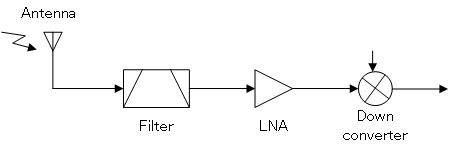
Such devices are usually found at the RF front end of a receiver e.g. following a RF filter that passes the band of interest. As we have described, it is vital that the first amplifying device add as little noise as possible to minimise overall receiver noise.

An general example of LNA being used in a receiver
Example applications
Satellite receiving equipment
Low noise amplifiers can exist separately from the main receiver such as that used on television satellite parabolic "dish" antennas. As satellite signals use high frequencies these cannot be carried along conventional coaxial cable directly and so therefore require amplification and down conversion. The LNA in combination with a downconverter is combined into a single unit called the LNB (low noise block downconverter) that is placed at the antenna's feed point.
Signal loss between antenna and receiver
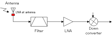
In situations where the receiver is located far away from the antenna (requiring a long coaxial cable), signal loss can be significant. Without amplification, the signal will be too weak by the time it arrives at the receiver input. To prevent this, a LNA can be installed at the antenna as shown:

LNA at antenna (shown in red)
Disadvantages of using LNA
An LNA amplifies signals which can introduce distortion and cause receiver saturation, particularly in the vicinity of strong signals.