What is 12 dB SINAD?
Introduction
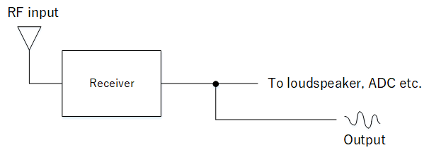
In this article, we talk about SINAD (signal plus noise and distortion) which is one way of measuring the sensitivity of a radio receiver. It is primarily used in radio receivers for voice, in particular FM receivers (AM and SSB is also applicable) and the measurement is performed on receiver's output (e.g. an audio signal).

Measuring the SINAD on an output signal
What is distortion?
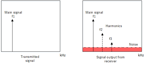
The SINAD allows the measurement of not only noise, but also distortion as well. But what do we mean by "distortion"?

Distortion and noise in the received signal.
In the image above, the signal to be transmitted is f1 (e.g. audio signal). However the receiver will also output noise and also the main signal harmonics, f2 and f3 and so on which are distortion products. While noise is an independent process, the harmonics are by products created from the interaction between the signal and receiver. In the context of audio receivers, these need to be minimised to allow for comfortable listening, especially when listening to broadcasts such as music. For reception of data signals (discussed later in this article), any distortion will increase the chance of a bit error, so we also need to reduce them here.
Obtaining the SINAD
As mentioned previously the signal to be measured is the output from the receiver. Below we will use an example with an FM handheld receiver whose output is obtainable through the line out or headphone socket.

Measuring SINAD
Setup parameters
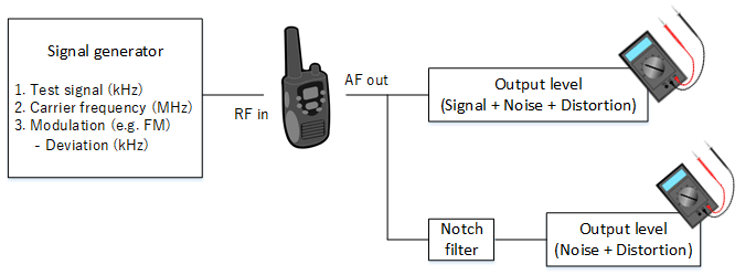
The RF signal to input to the radio receiver can come from e.g. a signal generator. The signal generator needs to be capable of outputting a modulated carrier whose level can be adjusted.
- Test signal (kHz): This is the test signal that will be heard at the receiver output (eg. 1 kHz).
- Modulation (e.g. FM) : This is how the test signal will be modulated onto the carrier. FM (for FM receivers) is typical. In the case when using AM or SSB radios, then that modulation can be used.
- Deviation (KHz) : For FM signals, this is the deviation (e.g. 3 kHz peak deviation for narrowband FM signals typically used in amateur communications).
Procedure
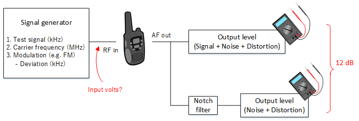
The signal generator outputs a carrier modulated by the test signal. This level must be adjustable and displayed preferably in volts (e.g. uV). This RF signal is applied to the receiver's antenna terminal and a suitable output (e.g. the receiver's line out or headphone) contains the signal to be measured. A measurement is taken of the complete output i.e. the signal + noise + distortion while a notch filter is used to remove just the test signal in order to allow measurement of noise + distortion only.
Calculating the SINAD
The SINAD is the ratio of the 2 measurements, i.e. the signal + distortion + noise to the noise + distortion:
$$ \text{SINAD} = \frac{\text{Signal + Noise + Distortion}}{\text{Noise + Distortion}} $$
The SINAD can be converted to dB as is often done. The conversion to be used depends on if the measurements were taken as voltage or power.
For measurements in watts:
$$ \text{SINAD (dB)} =10\log\left( \frac{\text{Signal + Noise + Distortion in watts}}{\text{Noise + Distortion in watts}}\right)\ $$
Since power is just square of the voltage, the formula if the measurements were taken in volts would be:
$$ \text{SINAD (dB)} = 10\log\left( \frac{\text{Signal + Noise + Distortion in watts}}{\text{Noise + Distortion in watts}}\right)\ = 20\log\left( \frac{\text{Signal + Noise + Distortion in volts}}{\text{Noise + Distortion in volts}}\right)\ $$
Since the numerator is the total of all the signal, noise and distortion, a SINAD value in dB will always be positive.
The 12 dB SINAD point
For speech that can be intelligently heard, the level of the noise + distortion in volts should not exceed 25% of the total output. To show how this corresponds to 12 dB SINAD can be explained as follows:
$$ \frac{\text{Signal + Noise + Distortion in volts}}{\text{Noise + Distortion in volts}} = 4 \text{ (i.e. 25% is noise and distortion)} $$
Substituting this into the formula for log voltage, we get:
$$ \text{SINAD (dB)} = 20\log{4} \approx \text{12 dB}$$
The voltage input (typically in uV) to the receiver antenna is increased until the 12 dB SINAD point is reached. You will see specifications of SINAD expressed as " so many uV at 12 dB SINAD" meaning "the voltage to the antenna input that produces 12 dB of SINAD". The lower this input voltage, the more sensitive the receiver is considered to be.

The 12 dB SINAD is the voltage input that produces a SINAD of 12 dB
If it is necessary to obtain the power input level to the receiver rather than voltage, you can use the formula as below, assuming an antenna impedance of 50 ohms.
$$ \text{Power (W)} =\frac{V^2}{50} $$
Or use our calculation tool here to convert between voltage and power.
Measuring sensitivity in radio modules
You might ask how SINAD might apply to radio modules that communicates data instead of e.g. audio.
A signal, be it an audio or data pulse are still signals that vary continuously with time. In that sense, the carrier is still modulated by an analogue signal. So a pulse representing e.g. a high signal is input to the transmitter and the receiver then outputs the same pulse. Such output would present to the external hardware (e.g. a CPU), a signal containing binary ones and zeros.
However the received pulses, as they are, will contain noise and may not be at the correct voltage levels for the external hardware. So in the receiver, a threshold circuit makes a judgement and converts the pulses to long high and long low signals at the correct voltage level. In order that the threshold circuit makes the correct judgement, the signal presented to it needs to be as free as possible of any noise. If the noise causes the threshold to identify the wrong bit level, we will get a bit error.

Threshold detection. In this case, the output prior to threshold can be accessed.
Therefore the tendency for a bit error to occur in a communication system partly depends on the noise and distortion performance of the receiver part (in addition to the minimum input power to the antenna which is another way of showing sensitivity). In order to measure this, if the received signal prior to the threshold circuit can be accessed, we can measure the SINAD of this signal. Since data is transmitted instead of audio, the 12 dB SINAD point has no meaning here - in fact the objective is to maximise the SINAD so we can minimise the chance of a bit error.
So why do we use 12 dB SINAD here?
The reason for using the 12 dB SINAD is just convention to be able to compare the receiver performance across multiple modules. In other words, we can apply the same measurement procedure as we would for conventional analogue radio receivers.