- Overview
- Details
- Documents
- Dev. tools
- Accessories
- Applications
- Case study
- FAQ
- Sales Network
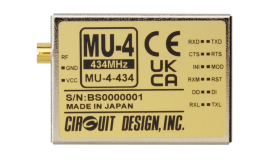
The MU-4-434 is an embedded radio modem operated in the 434 MHz ISM band designed as the successor to the MU-2-R with improved in-band blocking performance. Dedicated commands, designed for wireless applications, are provided for building a range of wireless system, from simple control systems to wide network systems. Using the commands, the user can concentrate on designing the application without needing to be aware of the radio protocol and control aspects. Reed-Solomon code is used for forward error correction (FEC) to maintain data integrity and provide highly reliable wireless communication. The MU-4-434 meets the requirements of the European RED and UK Radio Equipment Regulations 2017, carries the CE marking and UKCA marking.
The relay feature allows you to extend the range by using additional units (up to 10 units)
Features
- UART interface with simple command protocol compatible with MU-2-R
- 434 MHz ISM band Pre-programmed 127 channels
- 10 mW / 1 mW power selectable
- Forward error correction with Reed Solomon coding
- Repeater and auto answer back function
- Target station receive signal and noise level acquisition
- Low power operation 42 mA at 3 V / TX
- Transparent mode
- RED compliant (EN300 220)
- Radio Equipment Regulations 2017 (UK)
- 429 MHz version available (Japan)
Serial Data Transmission with Simple, Dedicated Commands
The MU-4-434 uses Circuit Design’s unique simple, dedicated commands. Setting channels and all other controls can all be performed with commands.
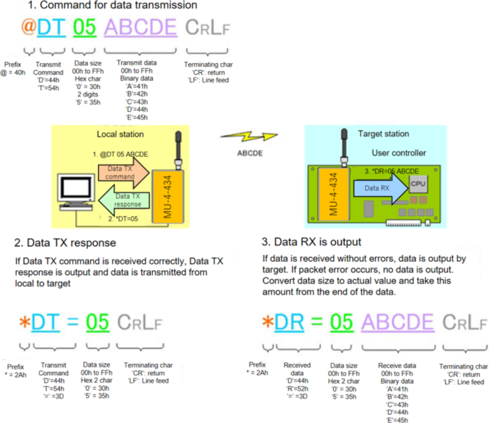
Example 2: Changing the channel to 08
@CH08
Note: The command transmission is the same for MU-2-R, however there exists timing differences between
MU-2-R and MU-4-434
Relay Function (Maximum 10 Stations)
You can make a relay with a maximum of 10 stations using the route command.
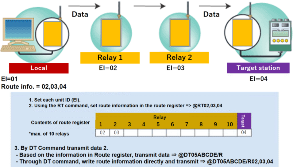
Example of transmitting data (ABCDE) to the target station with Equipment ID EI=04 via relay station 1 (EI=02) and relay station 2 (EI=03).
MU-4-434 and MU-2-R should not be used together when using relay or ACK function. For more information, please contact Circuit Design.
Reed Solomon Coding
One of several FEC block codes, it has strong error correction ability and the characteristic of correcting data errors caused by burst noise. Reed-Solomon codes are used in compact disks, satellite communications, and digital TV broadcasting
MU-4-434 FEC
The MU-4-434 uses Reed-Solomon code for FEC, which reduces errors occurring due to burst noise and/or noise at low received signal level, and it improves the receive sensitivity of the equipment by more than 5 dB *1.
| Error correction protocol data format *2 | MU-4-434 data block | |||
|---|---|---|---|---|
| MU-4-434 data component: 1 to 255 bytes variable | User data | Parity | ||
| Reed-Solomon code specification | Code: RS (255, 247) | 1 - 32 bytes | 8 bytes | |
| Primitive polynomial: X8 + X4 + X3 + X2 + 1 | 33 - 64 bytes | 8 bytes | ||
| Interleave: None | : | : | ||
| Error correction rate: 10% error or more | 224 - 225 bytes | 8 bytes | ||
*1 In interleave mode / Measured at Circuit Design, Inc.
*2 There are operation modes with or without error correction. Select the appropriate mode depending on the situation at the site and the application
How, When Does FEC Help RF Communication
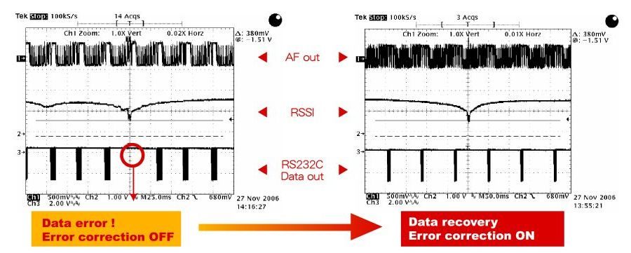
VS Error in burst noise (Measurement conditions: 4,800 bps / Data size 4 bytes)
Error correction reduces influence from noise with is generated suddenly or is continuously generated at a dead point during mobile use with multi path.
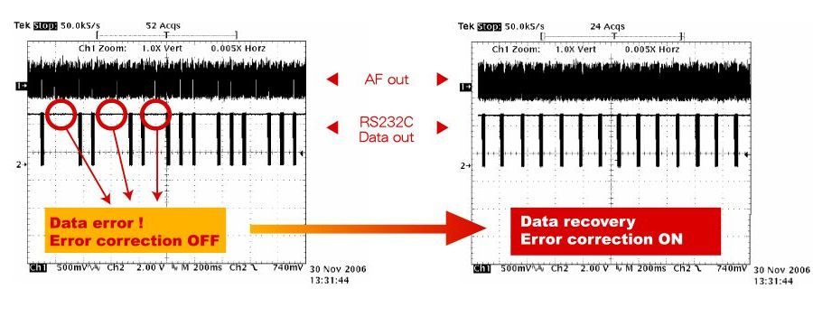
VS Error in random noise (Measurement conditions: 4800 bps / Data size 32 bytes / Received signal level -114 dBm)
Error correction reduces influence from random noise which appears at a low received signal level
Target Station Receive Signal and Noise Level Acquisition
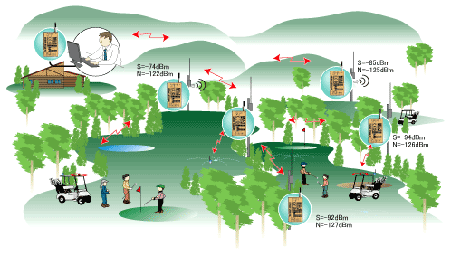
It is possible for the main station to acquire the signal and noise level of the target station some distance away. By using these values (and therefore calculating SNR), it is possible to evaluate the communication conditions during installation.
Applications
- Telemetry - Environment monitoring, Meter reading, Various measuring applications
- Telecontrol - Remote control for industrial equipment
- Security - Various alarm and monitoring systems
Specifications
General
| Parameter | Specification | Remarks |
|---|---|---|
| Applicable standard | RED compliant (EN 300 220) UK Radio Equipment Regulations 2017 |
CE marking and UKCA marking acquired |
| Communication method | Half-duplex, one-way, broadcast | |
| Oscillation system | PLL synthesizer system | |
| Emission type | F1D | Binary FSK |
| Frequency | 433.200 to 434.775 MHz | |
| Number of channels | 127 channels | 12.5 kHz step |
| RF bit rate | 4,800 bps | |
| RF output power | 10 mW / 1 mW | Nominal, Contact (50 Ω) |
| Receiver sensitivity | -113 dBm | Transparent mode, BER 0.1% |
| Error correction system | Reed-Solomon code | RS (255, 247) |
| Supply voltage | 3.0 to 5.0 V DC | Absolute maximum rated voltage 5.5 V |
| Supply current | Transmitting: 42 mA Receiving: 22 mA |
10 mW at 3 V |
| Transmitting: 26 mA Receiving: 22 mA |
1 mW at 3 V | |
| Operating temperature range | -20 to +65 ºC | The operation distance varies with the temperature conditions. |
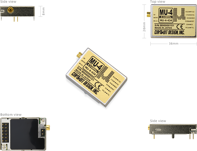
| Dimensions | 36 × 26 × 8 mm | Not including the antenna. |
| Weight | 14.5 g |
Reference data
* Effective radio communication speed: About 3,400 bps / Conditions: One-way communication, no error correction, 25 ºC
* Range: About 600 m / Conditions: One-way communication, no error correction, 25 ºC, line of sight distance, ground level of 1.5 m, vertical antenna
UART Interface
| Parameter | Specification | Remarks |
|---|---|---|
| Communication method | Serial communication | RS232C format |
| Synchronization | Asynchronous | |
| UART bitrate | 1,200 / 2,400 / 4,800 / 9,600 / 19,200 / 38,400 / 57,600 bps | |
| Other parameters | Data length 8 bits, no parity, 1 or 2 stop bits |
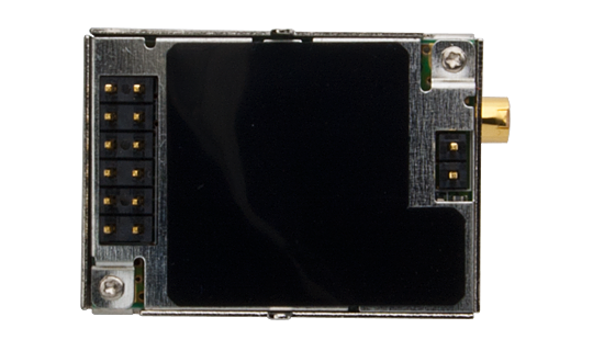
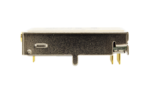
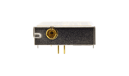
External View
Operation Guide
| Version 4.0 |
|---|
Application Notes
| How to use relay function for MU-2-R and MU-4 module | |
|---|---|
| Installing the USB driver on Windows 8 and 10 (MU4-USB) | |
| Operating the MU-4 in transparent mode |
Certifications
| DoC for CE (MU-4-434) | |
|---|---|
| DoC for UKCA (MU-4-434) |
Parts Change Notice (PCN)
| PCN2391001 (Oct. 2023) |
|---|
Supplementary Information
MU2-ESP
Operation guide
| MU-2-R Evaluation Software Program (Version 1.1) |
|---|
Evaluation Program
| Evaluation program* for MU-4-434 and driver |
|---|
* The evaluation software for MU-2-R can be used to evaluate the MU-4-434
Supplementary Information
| Demonstration of evaluation software for embedded radio modem MU-2-R |
|---|
Test Board for MU-4-434
RS232 Interface Board : MU4-RS2IF
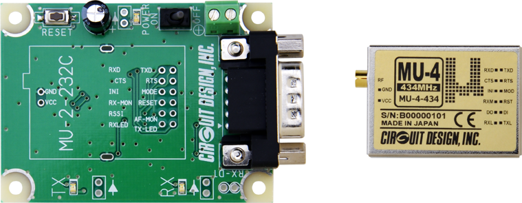
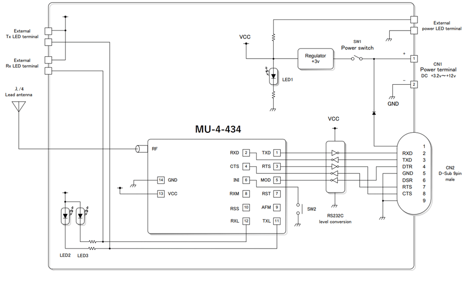
The MU4-RS2IF is an RS232 interface board for testing MU-4-434 module. It can connect to the COM port of PC or PLC through the D-Sub-9 pin connector. The board is equipped with transmit, receive LED, power supply terminal, main switch and initialisation button.
The module can be used with coax extension cable to allow optimum placement of the antenna according to the environment. Click here for more details.
This test board does not include the modem MU-4-434. Please order if necessary.
Features
- Connection to PC COM port for data communication and module control
- Using RS232 cable, extension to tens of meters possible.
- Evaluation program available
External View
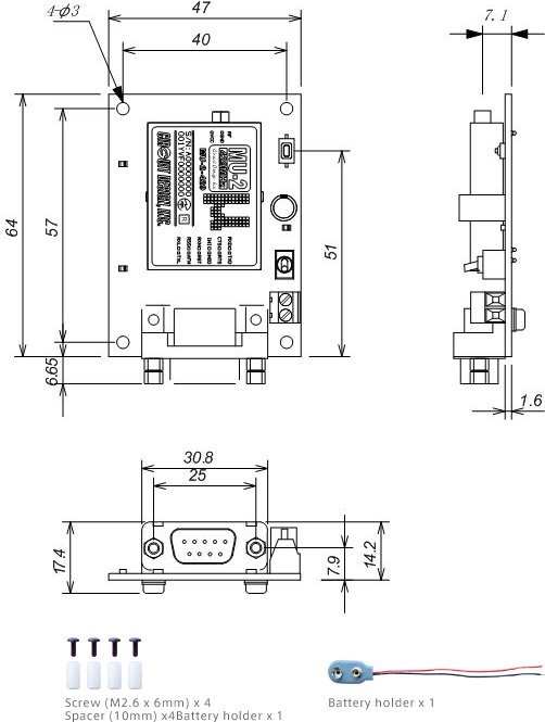
USB Interface Board : MU4-USBIF
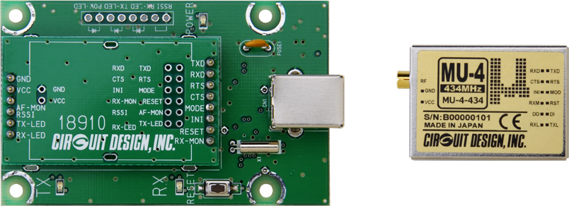
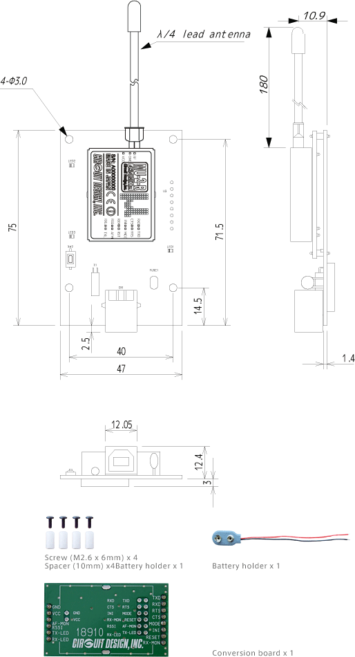
The MU4-USBIF is a USB interface board for testing MU-4-434 module. It can connect to the COM port of PC or PLC through USB. The board is equipped with transmit, receive LED, power supply terminal and main switch.
The module can be used with coax extension cable to allow optimum placement of the antenna according to the environment. Click here for more details.
This test board does not include the modem MU-4-434. Please order if necessary.
Features
- Connection to USB port for data communication and module control
- Evaluation program available
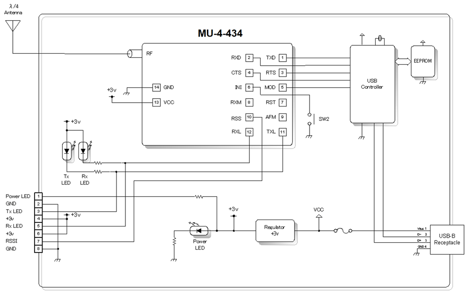
External View
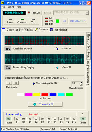
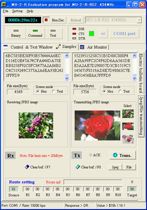
Evaluation Program: MU2-ESP
The MU-4-434 can be tested using the MU2-ESP evaluation program. The description of the functions in the evaluation program is listed below. To download the evaluation program, please click here.
Air Monitor
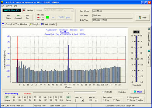
Spectrum Domain
This displays the receive level of each frequency channel within the band as a simple spectrum. You can monitor the noise and the state of interference in the field. You can also display the information for the target station.
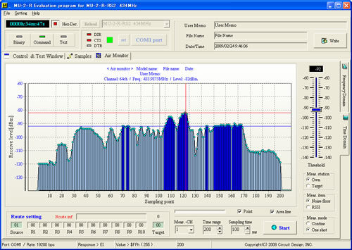
Time Domain
This records the receive level of specific channels in a time base. You can monitor changes in the field strength due to the communication distance and environment of use.
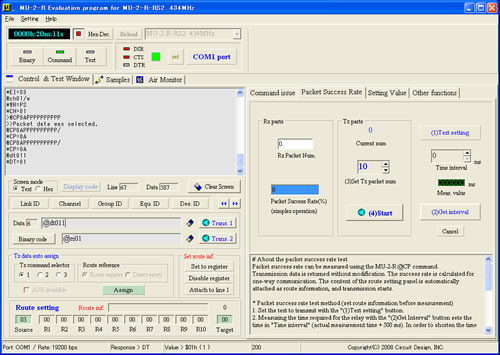
Control Window
You can issue commands and perform controls.
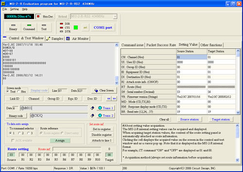
Test Window
You can perform packet success rate tests and acquire the internal setting values.
Communication Test
Using an RS-232C conversion board, you can perform RS232C communication tests between PCs.
Text Transmission
File Transmission
Accessories
ANT-LEA-01-R

Lead antenna with plug
...more infoANT-RIG-01-R

Rigid antenna with plug
...more infoCBL-TMP-01-R

Coaxial cable
...more infoANT-01-R
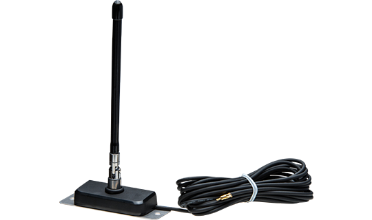
434MHz antenna with extension coaxial cable for the receiver
...more infoCBL-BNC-01-R
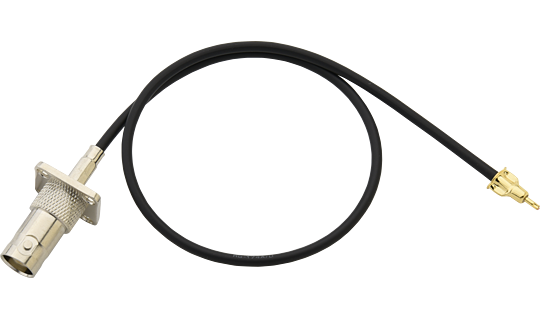
BNC Connector conversion cable
...more infoAC-400-R
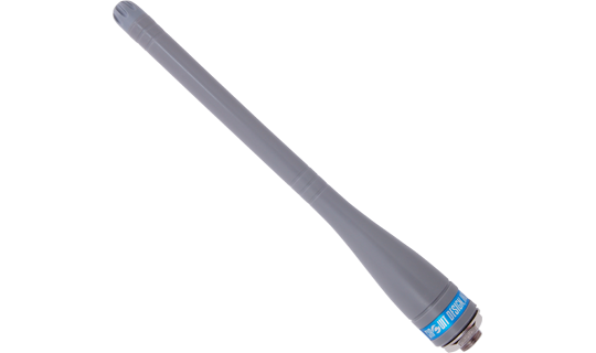
Water Resistant Antenna Cover
...more infoCBL-SMA-02F-R
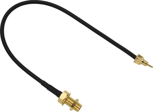
TMP-SMA conversion cable
...more info![[ Video ] [ MU-2-R ] - Demonstrating the Windows evaluation program for the MU series of modems.](https://www.cdt21.com/wp/wp-content/uploads/2023/01/mu-2-r_demonstrating-the-windows-evaluation-program.png)
[ Video ] [ MU-2-R ] - Demonstrating the Windows evaluation program for the MU series of modems.
![[ Video ] [ MU-2-R ] - Introducing the low power RF modem for the ISM 434 MHz band.](https://www.cdt21.com/wp/wp-content/uploads/2023/01/mu-2-r_introducing-the-low-power-rf-modem-for-the-ism-434mhz-band.png)
[ Video ] [ MU-2-R ] - Introducing the low power RF modem for the ISM 434 MHz band.
![[ Video ] [ MU-2-R ] - Demonstrating how to send some sensor readings using Arduino and the low power transceiver MU-2-R.](https://www.cdt21.com/wp/wp-content/uploads/2023/01/mu-2-r_demonstrating-how-to-send-some-sensor-readings-using-arduino-and-the-low-power-transceiver-mu-2-r.png)
[ Video ] [ MU-2-R ] - Demonstrating how to send some sensor readings using Arduino and the low power transceiver MU-2-R.
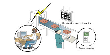
MU-4-434 Application examples
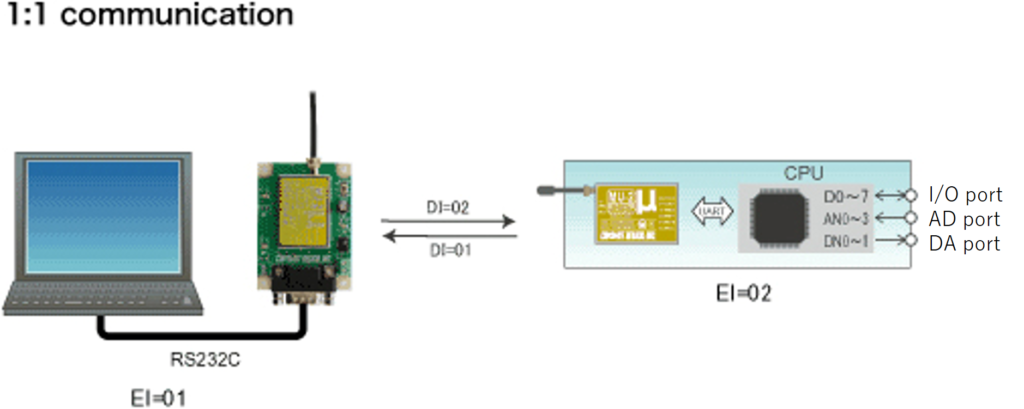
MU-4-434 System examples
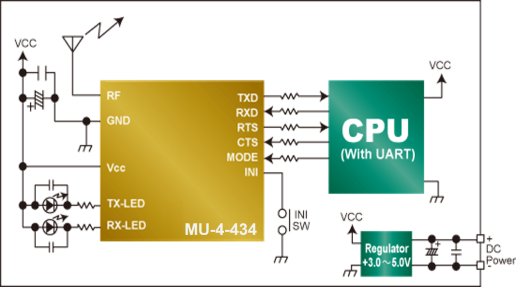
MU-4-434 Connection examples
-
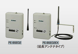
RF modem using LoRa® in the 429 MHz band: Machine monitoring system
SLR-429M
The system is capable of obtaining information about various machines in the factory while forwarding it to a central management system in order to visualise their status and in realtime. Collected data can be exported to CSV file and if a machine stops for any reason, it is possible to notify by email to the operator automatically. By using the long range SLR-429M LoRa modem operating in the 429 MHz band for machine monitoring, large scale cable installation for communication is not required. Such IoT system can be introduced in a short time and at low cost.

-
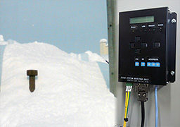
KANTARO system to detect ground slope collapse - transmitting the sensor data by wireless
MU-2-429
Gradual shifts in tilt can occur in natural or artificial ground slopes due to factors such as looseness and slipperage. The KANTARO was developed for capturing such shifts.
Measurements from the tilt sensor driven into the ground slope are taken at regular intervals. Changes in the tilt and the speed of change are determined and the level of risk evaluated. The data from the tilt sensor and information that could indicate imminent ground collapse can be transmitted quickly by radio making this useful in disaster prevention.
Company name
Chuo Kaihatsu Corporation
-
Remote monitoring using long range wireless communication - System for monitoring sewage manhole pump
MU-3-429, MU-2-429
In the case where problems occur in infrastructure essential to daily living such as the sewage system's water level or pump, a swift response is required. The ICT sewage monitoring system that uses low power radio makes this possible. By using long range wireless communication for monitoring, it is possible to identify the source of the problem as soon as it occurs. This allows the sewage system to be operated and maintained safely.
- What is transparent interface?
- Is communication between the MU-4 and STD-302Z possible?
- What does Forward Error Correction mean in the MU-4 module?
- How do I set the User ID on the MU-4?
- I want to replace the existing wired connection (RS-232C) with the MU-4. With the existing connection only TXD and RXD are used. Is it possible to go wireless with the MU-4?
- Is the MU-4 included in the MU4-RS2IF and MU4-USBIF test board?
- Is it possible to use the MU4-RS2IF in combination with the MU4-USBIF?
- What is the make and model of the LED on the MU4-RS2IF test board?
- What do I need to be careful of when interfacing between the single-chip CPU and the MU4-RS2IF?
- Does the MU-4 have power-saving and standby modes?
- What is the Air monitor feature?
- According to the Operation Guide, the MODE terminal must be set to L to use the MU-4 in the binary mode, but is it necessary to connect the MODE terminal to the GND terminal?
- Can you connect MU-4 with RS-485?
- How do you protect the mounted MU-4 from noise?
- What error detection systems do you use in MU-4?
- Can I use Visual Basic (VB) to make a control program for the MU-4?
- What is the purpose of MU-4 User IDs?
- Is it possible to send binary data with the MU-4?
- How do you set the MU-4 to binary mode when turning on the power?
- What OS can I use MU4-USBIF on?
- When I tried to open the COM port with the MU-4 Evaluation Program, the message 'Can't Open the Port. Please check the hardware.' appeared and the connection failed.
- Can I use the MU-4 with Linux?
- Why do I lose the parameter settings of the MU-4, when power is disconnected?
- What is the maximum communication distance for relay systems?
- How can the RSSI value be obtained when the MU-4 is in binary mode?
- There is no change in RTS output. It is always Low. Is this OK?
- Can you check the communication content between two MU-4 units using a third unit?
- Every time 'Open port' in the MU2-ESP is clicked, 'Framing error' is displayed.
- Can I connect Circuit Design modules to Arduino or Raspberry Pi?
- I want to put the RF module in my enclosure? What do I need to be careful of?
- There is a problem with communication range. What is the problem? What should be checked?
- How should the antenna be handled?
- I need help in selecting a CPU to control my module?
- Can Circuit Design module communicate with a tablet?
- I'd like to use my own antenna on your module. Where can I find the suitable connector (e.g. SP060022)?
