Analogue modulation
Introduction
Modulation is the application of an input signal (e.g. voice signal from a microphone) to a constant amplitude/frequency signal called a carrier wave by continuously varying (amplitude, frequency or phase) of the carrier. It is this carrier wave that "carries" information about the input signal which is transmitted and received. At the receiver a process called demodulation is able to extract the original input signal from the carrier. In the case of FM radio, it can feed this signal to a loudspeaker.
Purpose of modulation and demodulation
The antenna size generally varies by frequency. Since baseband signals such as voice occurs in the frequency range 20 Hz - 20 kHz, an antenna to radiate this signal directly would need to be several kms long! Therefore by using a carrier with a much higher frequency (e.g. MHz range), antennas can be made just a few metres in length.
Another reason is channelisation. By using many carriers with different frequencies, signals can be organised into channels in a frequency band. Communication can occur on several channels simultaneously without interference (this would not be possible if the signal was transmitted directly with no modulation). Once the receiver tunes into a single channel it can perform the demodulation process.
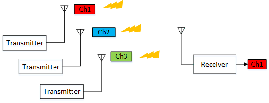
The following discusses how to change the carrier to convey information.
- Amplitude modulation or AM: Change the amplitude in response to an input signal.
- Frequency modulation or FM : Change the frequency in response to an input signal.
- Phase modulation or PM : Change the phase in response to an input signal. This is one of the principal methods of angle modulation, the other being FM.
Amplitude modulation
Amplitude modulation or AM changes the amplitude of the carrier in response to the input signal. Most will be familiar with AM broadcasting on the short, medium and long wave bands. Less familiar applications include airband communication using voice and amateur radio.
The advantages of AM is the simplicity and low cost when it comes to equipment design. The disadvantages are poor noise immunity (since noise causes changes in amplitude) and poor spectral efficiency since the sidebands carry only a fraction of the total power (the rest is in the carrier wave which is also transmitted).
Theory
Assume our message signal m(t) is a simple audio tone of frequency Fm (in KHz) with amplitude Am. To represent this wave in the time domain t, we just apply the equation for a standard sine wave (or cosine wave) with amplitude Am and frequency Fm.
$$m(t) = A_m\cdot\cos(2\pi\cdot F_m\cdot t) $$

Our carrier is also a pure sine wave generated by an oscillator in the transmitter. The carrier frequency is represented by Fc with wave amplitude Ac and phase offset \( \phi_c \). The carrier frequency is purposely designed to have a much higher frequency (e.g. MHz range):
$$c(t) = A_c\cdot\cos(2\pi\cdot F_c\cdot t + \phi_c) $$

The message expressed as (\(1 + K_{am}\cdot m(t)\)) is multiplied with the carrier c(t) to produce our modulated signal s(t). You can see how this allows the carrier amplitude Ac to vary with m(t).
$$s(t) = [1 + K_{am}\cdot m(t)]\cdot \overbrace{A_c\cos(2\pi\cdot F_c\cdot t + \phi_c)}^{c(t)} $$
Note how the carrier is preserved during transmission even when m(t) is 0.
If we assume that m(t) is our audio tone mentioned, then by substituting for m(t), we get our final modulated wave:
$$s(t) = [1 + K_{am}\cdot \overbrace {A_m\cdot\cos(2\pi\cdot F_m\cdot t)}^{m(t)}]\cdot \overbrace {A_c \cos(2\pi\cdot F_c\cdot t + \phi_c)}^{c(t)} $$
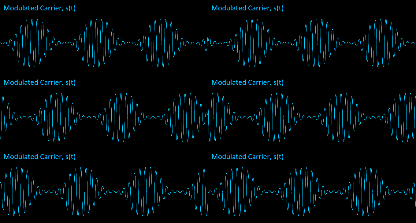
Notice how the final waveform contains the shape or envelope of our audio message m(t). Kam is called the modulation index m.
AM spectrum
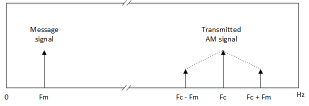
Earlier we talked about how AM is poor in terms of spectral efficiency. If a spectrum of an AM signal is examined we can see our single message signal has translated into 3 new signals during transmission. If Fm is our message signal, the resulting RF spectrum contains a sideband spaced Fm Hz on either side of our carrier, Fc. This means our transmitted signal occupies twice the bandwidth of our message signal. This is made worse by the fact that the 2 sidebands are exact copies, so in theory only one is necessary for the receiver to re-construct the original message signal.
Modulation index for AM
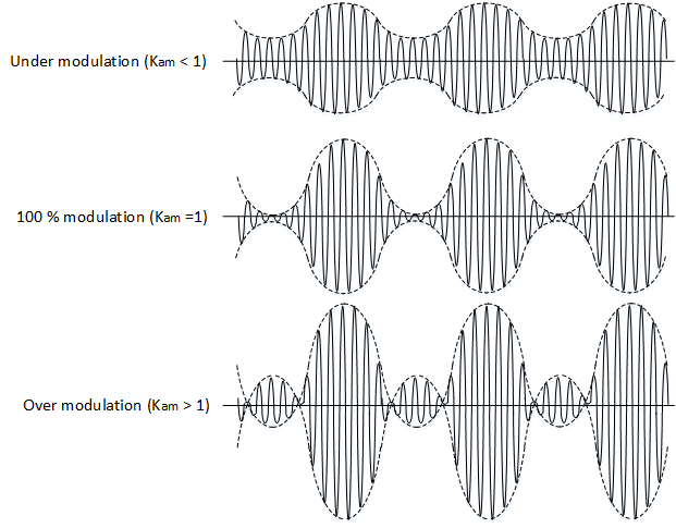
The modulation index or m for AM can be described as the degree to which the carrier is being modulated by the message signal. To avoid distortion we must set m to be as close to but not exceed 1 (overmodulation).
AM demodulation
To receive AM, there are 2 methods.
- Envelope detection : Rectify the signal and apply low pass filter.
- Synchronous detection : Multiply the incoming signal with a carrier identical in frequency and phase of the carrier at transmitter. For AM, since the carrier is preserved during transmission, the receiver can extract this to perform demodulation.
DSBSC and SSB
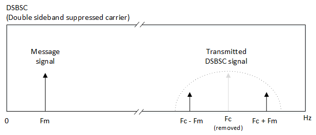
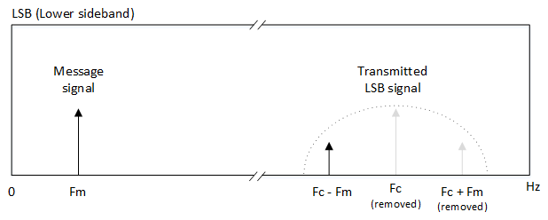
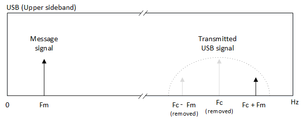
To improve spectral efficiency for AM, there are variations on AM which involve suppressing the carrier or one of the sidebands. This increases electrical efficiency as all the power can be distributed to the sidebands.
DSBSC (Double sideband suppressed carrier) suppresses the carrier but keeps both sidebands. SSB (single sideband) suppresses the carrier and keeps only one of the sidebands (USB = upper side band, LSB = lower side band)
DSBSC and SSB demodulation
The demodulation is the same for AM, however it requires the insertion of a local carrier by the receiver to perform the demodulation.
Frequency modulation
Invented in 1933 by Edwin Armstrong, frequency modulation or FM is another modulation technique to AM, the difference being instead of amplitude, its the frequency of the carrier that is varied with the message signal m(t). FM has several advantages over AM and is generally used for high fidelity music and speech on FM radio. Frequencies for FM tend to take place at higher frequencies (such as the VHF or UHF range).
Theory
Assume our message signal m(t) is a simple audio tone of frequency Fm (in KHz) with amplitude Am. To represent this wave in the time domain t, we just apply the equation for a standard sine wave (or cosine wave) with amplitude Am and frequency Fm.
$$m(t) = A_m\cdot\cos(2\pi\cdot F_m\cdot t) $$

Our carrier is also a pure sine wave generated by an oscillator in the transmitter. The carrier frequency is represented by Fc with wave amplitude Ac and phase offset \( \phi_c \). The carrier frequency is purposely designed to have a much higher frequency (e.g. MHz range):
$$c(t) = A_c\cdot\cos(2\pi\cdot F_c\cdot t + \phi_c) $$

In FM, values of m(t) would vary the carrier frequency above or below Fc. Remember that trigonometric functions describes waves as a function of phase rather than frequency (making FM another form of phase modulation). Since frequency is the derivative of phase, \(\frac{d\phi}{dt}\) we can convert frequency variations into phase variations by taking the integral of m(t).
$$s(t) = A_c\cdot\cos(2\pi\cdot F_c\cdot t +K_{fm}\int_{-\infty}^t m(t) dt + \phi_c) $$
Kfm is defined as:
$$ K_{fm} = \frac{2\pi \Delta f}{|m(t)|_{max}} $$
where \( \Delta f \) is the frequency deviation and represents the maximum frequency shift in the carrier corresponding to the maximum value of m(t).
Assume that m(t) is our audio tone from earlier. This is a simple sine wave tone, so the maximum m(t) can be is Am. Then Kfm will become
$$ K_{fm} = \frac{2\pi \Delta f}{A_m} $$
Substituting for Kfm, m(t) and putting \( \phi_c \) = 0, our final equation for the frequency modulated wave s(t) becomes:
$$s(t) = A_c\cdot\cos(2\pi\cdot F_c\cdot t +K_{fm}\int_{-\infty}^t A_m\cdot\cos(2\pi\cdot F_m\cdot t) dt ) $$
$$= A_c\cdot\cos(2\pi\cdot F_c\cdot t +\frac {\Delta f}{F_m}\cdot\sin(2\pi\cdot F_m\cdot t)) $$

Notice how the carrier frequency sweeps between low and high frequencies corresponding to the minimum and maximum in our sine wave audio tone m(t).
The \( \frac {\Delta f}{F_m} \) is the modulation index m for FM.
Comparison with phase modulation or PM
Both frequency modulation and phase modulation represent angle modulation and in some instances can look identical.
For phase modulation, the phase is shifted by m(t). In other words, we can write the formula generally as:
$$s(t) = A_c\cdot\cos(2\pi\cdot F_c\cdot t + m(t)) $$
We can see that m(t) operates directly on the phase making phase modulation slightly more intuitive to understand than FM. Despite this, PM is not so common in analogue communication and finds its use mainly in digital communication.
Modulation index for FM
We describe the FM modulation index as a measure of how sensitive the carrier frequency changes are to m(t). For low values of m, the frequency deviation is low and the shifts are not as noticeable as shown below.
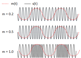
For values of m below 0.5, the signal is described as narrowband and when it is 1 or more, the signal is wideband.
Due to the wider bandwidth available, wideband is used in FM broadcast for high fidelity audio. Narrowband is used in mobile communications where high fidelity is not required, but more the need to fit channels in a limited bandwidth space.
FM spectrum
The spectrum of an FM signal is not so simple to analyse as AM. For AM there existed only 2 sidebands (upper and lower). In an FM modulated signal there are an infinite number of sidebands spaced Fm Hz intervals away from the carrier. This would imply infinite bandwidth to carry an FM signal which would make the system unfeasible.
Fortunately, the sidebands decay in amplitude with distance from the carrier, so by using Carson's rule, we have a way of approximating the bandwidth by only considering those sidebands above a certain level.
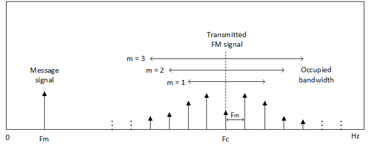
We can see that for higher m, the occupied bandwidth increases. For example, broadcast FM uses frequency deviation of 75 kHz and allocated a 200 kHz wide channel. We can see that the maximum frequency in the audio can be no higher than 25 kHz and the modulation index is 3. This qualifies it as wideband FM.
FM demodulation
To receive FM, frequency discrimination or PLL detection method is used.
