Gain (EIRP and ERP)
Introduction
This article discusses antenna gain, EIRP (Effective Isotropic Radiated Power) and ERP (Effective Radiated Power). EIRP, ERP and gain describe how the transmitter output power is transformed into radiation power emitted by the transmitting station. The reason why EIRP and ERP calculations are useful is that they take into account the transmitter output power, any losses and gain of the antenna used. Thus these calculations can be used to select an appropriate antenna if the EIRP and ERP values are known.
What is antenna gain?
To explain gain (or specifically antenna gain), it is easier if we look at the radiation patterns for various antennas. For example, compare a half-wave dipole and an isotropic antenna radiation patterns:
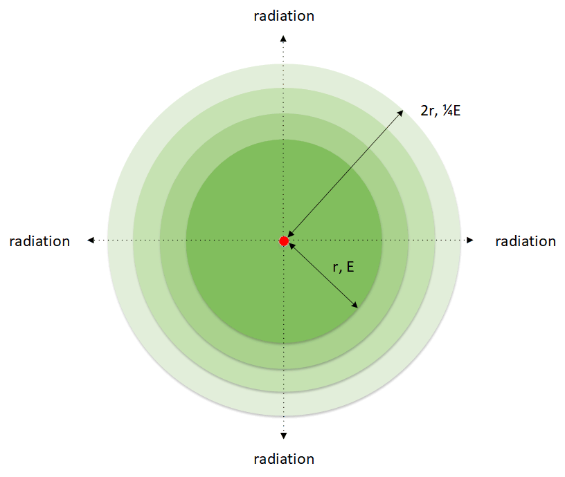
Radiation pattern produced by an isotropic emitter
(red centre point)
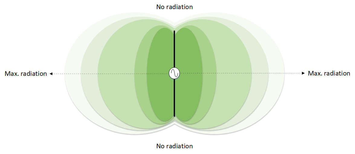
Radiation pattern for half-wave dipole
By looking at the radiation patterns above, we can determine some points:
- An isotropic antenna has equal radiation in all directions. The pattern is spherical.
- Real antennas (e.g. the half-wave dipole) concentrate the emitted power in some areas and reduce it in others. Their radiation patterns contain null and peaks.
- The antenna gain is calculated along the axis where the peak level emission occurs.
How do we quantify gain?
First we must define how gain is calculated. Power gains are stated by comparing the measured power level (P) against a known reference value Pref i.e. as a power ratio. By taking the log of this and multiply by 10, we get:
$$Gain (dB) = 10 \times \log\frac{P}{P_{ref}}$$
To illustrate the dB scale graphically, we can compare the gain with its equivalent value in dB. The green positive values show positive gain (i.e. increase over the reference value) and the red values show negative gain (i.e. decrease over the reference value). A gain of 0dB indicates no gain.

The dB scale
In RF engineering, commonly known rules of thumb for power gains are +/-3 dB corresponding to doubling/halving and +/-10 dB corresponding to multiply/divide by 10 (note for voltage gain, the dB value is doubled i.e. +/-6 dB and +/- 20 dB). When RF elements are cascaded together, it becomes evident that instead of multiplying and dividing gain values, we can instead add or subtract them when they are expressed as dB.
Gain can also be used to express a power level against an arbitrary reference value. For example, using reference values of 1 W and 1 mW, power levels can be expressed in dBW (measured against 1 W) and dBm (measured against 1 mW) respectively. For example a transmitter with 1 W output power can be expressed as 0 dBW or 30 dBm. By expressing power level using dBW and dBm instead of watts, it becomes easy to include these in the calculation of EIRP and ERP.
To aid in the calculation of dBm and dBW, Circuit Design provides a technical tool here.
Applying this to antenna gain
Now that we have defined gain, how do we apply this to antennas? Well, we can measure an antenna's gain by comparing its emission power with that of a known antenna. For example, to measure the gain of a half-wave dipole antenna, we can compare it's peak emission level with an isotropic.
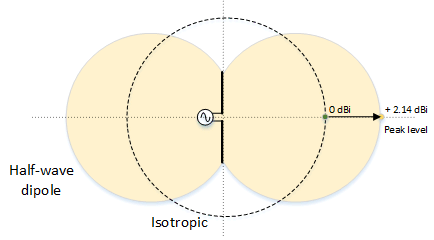
Isotropic and half-wave dipole emission
It turns out that this difference is about 2.14 dB. Since the half-wave dipole emission is higher than the isotropic in this respect, we say the half-wave dipole has a gain of +2.14 dBi. (the "i" means we are using an isotropic as a reference).
Gain does not always have to be measured against an isotropic. We can measure it against a half-wave dipole. In this case, the gain is expressed using dBd (the "d" means we are using the half-wave dipole as the reference). Since 0 dBd marks the peak level on the dipole emission (by definition), the isotropic level will be 2.14 dB below this or -2.14 dBd.
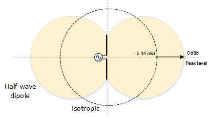
Isotropic and half-wave dipole (using dBd)
Gain misconception
It is important to understand that antennas are passive devices and do not amplify power - only that they distort the pattern to produce nulls and peaks giving the illusion of gain. The total emitted power is unchanged.
EIRP and ERP
Now that we understand antenna gain, we can use them in our calculation of EIRP and ERP.
Definition
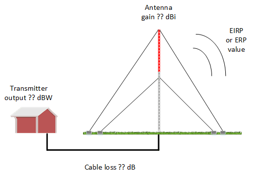
EIRP means Effective Isotropic Radiated Power and is more useful than just looking at transmitter output power. In other words, it is the maximum available radiation at the antenna after all power losses and gains in the system have been taken into consideration. Losses are subtractive and can be, for example cable loss. Gains are additive and can be gain in the antenna or an amplifier. Calculation of EIRP uses the following formula with PTx being the transmitter output power, LTx being transmitter losses and GTx being the antenna gain all expressed as dBW or dBm, dB and dBi respectively.
$$EIRP = P_{Tx} - L_{Tx} + G_{Tx} $$
For example, a transmitting station has 1000 W (or 30 dBW) as its transmitter output and uses an antenna with a gain of 10 dBi. The cable to the antenna introduces a 3 dB loss to the signal. The station EIRP would be:
30 dBW - 3 + 10 = 37 dBW (5011 W).
One way of visualising EIRP is that this value (37 dBW) represents the amount of power that an isotropic would have to radiate to achieve the same emission level as the station's transmitting antenna in its direction of peak emission.
In addition to EIRP, there is also ERP (Effective Radiated Power). Instead of using an isotropic as the reference, the standard half wave dipole is used. The formula for calculating ERP is the same as the EIRP except that the antenna's gain in dBd is used in the calculation:
$$ERP = P_{Tx} - L_{Tx} + G_{Tx} (dBd) $$
where GTx is the gain in dBd. To convert between dBi and dBd, the following formula is used:
$$ G_{Tx} (dBi) = G_{Tx} (dBd) + 2.14 $$
Similar to EIRP, ERP represents the value that a standard half-wave dipole would have to radiate to achieve the same emission level as the station's transmitting antenna.
How is EIRP and ERP useful?
Transmitting station
The various regulations that govern power levels may state their limits in either EIRP or ERP values. In this case, since these represent the final output power after transmitter power, losses and antenna gain have been taken into consideration, the designer can decide the transmitter output power, losses and the antenna type (and thus its gain) to be used in order that their equipment stays within the regulation limit.
EIRP and ERP are used when calculating link budgets. See the article on link budgets.
