How antennas radiate?
Introduction
The antenna is the most important component in any radio system as it is responsible for the transmission and reception of the radio signals. Even if a radio module is well designed it will never function optimally without a good antenna. In this page, we talk about basic antenna theory and later chapters will focus on practical antenna designs as there are often environmental constraints when designing real world antennas.
What is an antenna?
The antenna is an example of a transducer. That means it converts one form of energy to another, in this case electrical energy to electromagnetic energy. To help visualise this, we can consider how a microphone and loud speaker work.

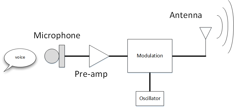
The loudspeaker is another example of a transducer because it converts electrical energy (signals from the microphone) to sound energy. These travel through the air as mechanical vibrations or as a sound wave.
The second diagram shows a basic model of a radio transmitter. Instead of a loudspeaker, an antenna converts electrical energy (from the modulator) represented by movement of charge carriers in a conductor to electric and magnetic fields (electromagnetic energy). These travel through the air as a radio wave. The below table summarises the main differences between sound and EM (Electromagnetic) waves.
| Speed | Oscillation | Medium | |
|---|---|---|---|
| Sound | 343 m/s (dry air, 20°C) | Longitudinal | Requires matter |
| EM wave | 300,000,000 m/s (vacuum) | Transverse | None |
The basic dipole antenna
We have established that EM waves are created by accelerating charge carriers. To allow charge carriers to oscillate, we need an alternating source voltage. What happens if we apply this to 2 open ended wires?
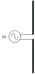
Below is what happens to the voltage and current distribution (blue and red areas) on the antenna across time. At first the voltage source, Vs causes current to flow. This current causes a magnetic field (shown by the circles around the wire). This magnetic field extends outwards 90 degrees to the dipole arms.
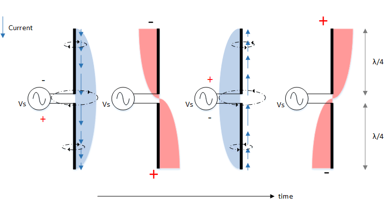
Since this circuit is open the current cannot flow beyond the ends of the dipole. This causes the charge carriers to accumulate at the ends resulting in an electric field being produced in parallel with the dipole. The magnetic field collapses since the current is now zero.
As the voltage source reverses, it causes current to flow in the opposite direction. The electric field collapses and the magnetic field forms once again. However as the current direction is now reversed, the magnetic field is now in the opposite direction (marked with arrows).
The process repeats with another electric field forming, this like the magnetic field is now in the opposite direction.
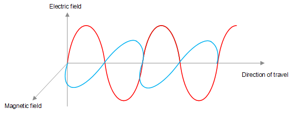
Since the electric field and magnetic field are perpendicular to each other and are alternating, the end result is an EM wave like below.
Resonance
Since the current changes with the voltage source it follows that the EM frequency produced must be the same as the frequency of the voltage source. If the current can be made to swing back and forth in the dipole arms in time with the voltage source frequency (for example on a swing, you push when the swing reaches the highest point and not before or after), you will get maximum radiation. This condition is called resonance and occurs when each arm is 1/4 wavelength (overall dipole length = 1/2 wavelength) long.
For example, a frequency transmission of 434 MHz, the wavelength is 0.69m. So for the dipole to be resonant at this frequency, it's length would need to be 0.35m.
Electrically speaking, resonance occurs when any reactance component of an antenna disappears leaving only the real resistances (radiation resistance and ohmic losses). Rather like how pure resistance heaters convert electrical energy to useful heat energy, the radiation resistance can be imagined to be converting the electrical energy in the dipole to the EM waves we want.
Radiation pattern
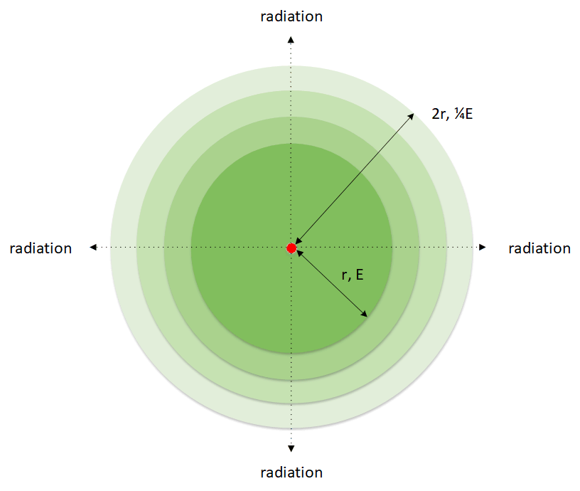
A point source of radiation (known as an isotropic source) would radiate uniformly in all directions as shown below. It follows the inverse square law, i.e. when doubling the distance from the source, the energy per unit area is reduced to 1/4.
An isotropic antenna cannot exist in reality, so in practice all antennas exhibit some kind of directivity in their radiation patterns. For example, the pattern emitted by our dipole is shown below. On the ends of the antenna, there is little or no radiation. However this would be fine for 360° coverage but not when you align the dipole horizontally.
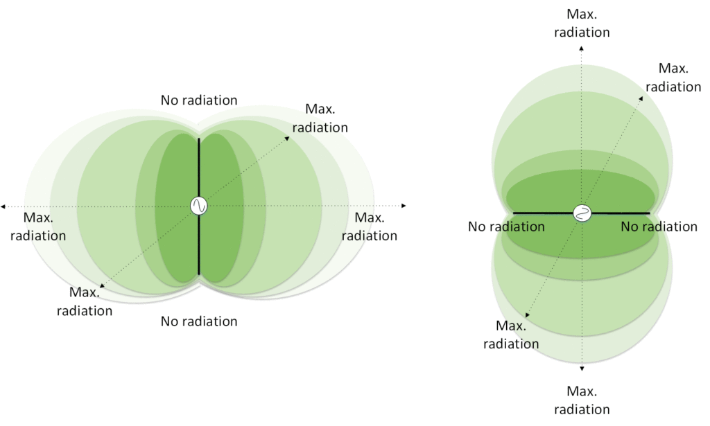
Generally, these patterns also apply when the same antenna is receiving in a sense that the antenna would be more responsive to signals from one direction and not the other. All types of antennas have their own radiation pattern which targets them at specific applications. Such topic will be discussed in future article.
