- Overview
- Details
- Documents
- Dev. tools
- Accessories
- FAQ
- Sales Network
![]()
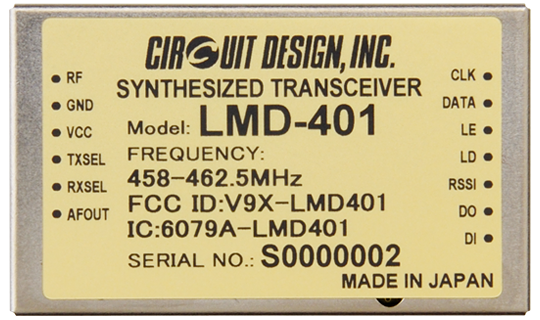
The LMD-401 is a low power narrow band synthesized transceiver with GFSK modulation. It is designed for use in the licensed band in North America and USA.
This is designed for use under FCC Part 90 Private Land Mobile Radio (PLMR) services and the ISED RSS-119 Industry Canada standard.
This simple, compact and low power transceiver is designed for embedding in user equipment and suitable for various low power industrial telecontrol and telemetry applications requiring high performance and reliability.
All high frequency circuits are enclosed inside a robust housing to provide superior resistance against shock and vibration. Using a TCXO as the reference oscillator circuit of the radio component ensures high frequency stability in wide temperature range.
Features
- Programmable RF channel with 12.5 kHz channel space
- 10 mW, GFSK 4,800 bps
- Low power operation 3.0 to 5.5 V, 46 mA(TX), 36 mA(RX)
- High receiver selectivity & blocking
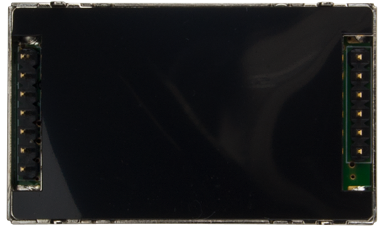
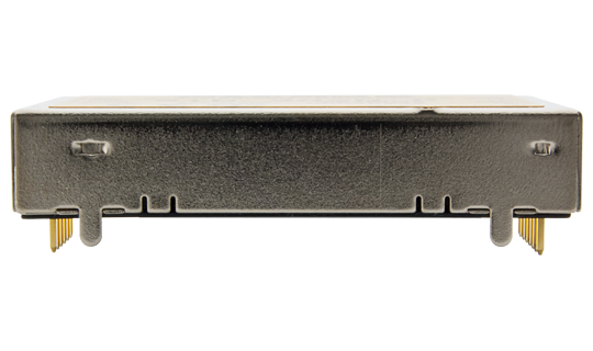
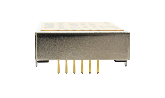
- Small size 50 x 30 x 9 mm
- Excellent mechanical durability, high vibration & shock resistance
- Wide operation range -20 to +65 °C
- ISED RSS-119 Industry Canada compliant
- FCC part 90 compliant
Applications
- Industrial remote control
- Telemetry
- Remote monitoring / Security
- Data acquisition/ SCADA
Other products related to this product
Specifications
Common
| Parameter | Specification | Remarks |
|---|---|---|
| Applicable standard | FCC Part 90.217 ISED RSS-119 |
|
| Communication method | Half-duplex | |
| Emission type | F1D | GFSK |
| Frequency | 458.000 to 462.500 MHz | |
| Channel spacing | 12.5 kHz Channel programmable | |
| RF bit rate | 4,800 bps | |
| Pulse width | Min. 200 us / Max. 15 ms | |
| Operating temperature range | -20 to +65 degree C | |
| Supply voltage | 3.0 to 5.5 V DC | |
| Supply current | 46 mA typ. (TX) 36 mA typ. (RX) |
|
| Dimension | 50 x 30 x 9 mm | |
| Weight | 25 g |
Transmitter Part
| Parameter | Specification | Remarks |
|---|---|---|
| Transmitter type | PLL synthesizer | |
| RF output power | 10 mW | |
| Data input | Digital L = GND, H = 3 V to Vcc | |
| Deviation | +/-2.4 kHz | PN9 4,800bps |
| Spurious emission | < -37 dBm (< 1000 MHz) < -31 dBm ( > 1000 MHz) |
|
| Adjacent channel power | -20 dBm | +/-12.5 kHz |
| Occupied bandwidth | < 8.5 kHz |
Receiver Part
| Parameter | Specification | Remarks |
|---|---|---|
| Receiver type | Double superheterodyne | |
| IF | 21.7 MHz (1st), 450 kHz (2nd) | |
| Maximum input level | 10 dBm | |
| Receiver sensitivity | -116 dBm typ. -116 dBm typ. |
12 dB SINAD BER 1% |
| Adjacent channel selectivity | > -50 dBm | +/-12.5 kHz |
| Blocking | > -20dBm | ±2MHz,±10MHz,±5% |
| Data output | Digital L = GND, H = 2.8 V |
Specifications are subject to change without prior notice
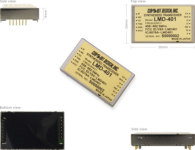
External View
Operation Guide
| Version 1.0 |
|---|
Application Notes
| Notes for radio module control using a CPU | |
|---|---|
| STD-302Z Interface Method | |
| PLL auto calculation sheet | |
| Data transceiver for use in the USA under FCC Part 90 License (LMD-401 458–462.5 MHz) |
Certifications
| FCC (LMD-401) | |
|---|---|
| ISED (LMD-401) |
Supplementary information
| Testing the radio modules STD-302Z and LMD-401 |
|---|
Evaluation Tools: TB-STD302
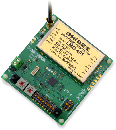
The test board TB-STD302 is equipped with a CPU which controls the PLL IC in the LMD-401.
Without making a PLL control program, you can perform data communication and range tests with the TB-STD302.
TB-STD302 does not include modules LMD-401. Please make sure to order it if needed.
Features
- Pre-programmed 365 channels in 458 - 462.5 MHz band
External View
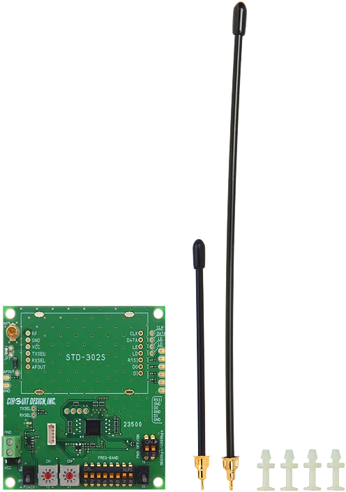
Antenna (ANT-RIG-01-R or ANT-RIG-02-R) x 1
Spacer x 4
Accessories
ANT-LEA-01-R
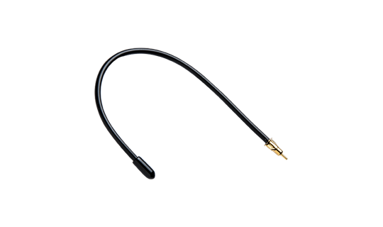
Lead antenna with plug
...more infoANT-RIG-01-R
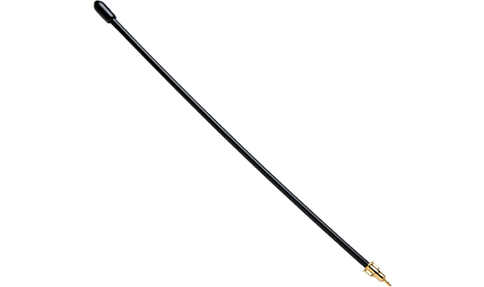
Rigid antenna with plug
...more infoCBL-TMP-01-R
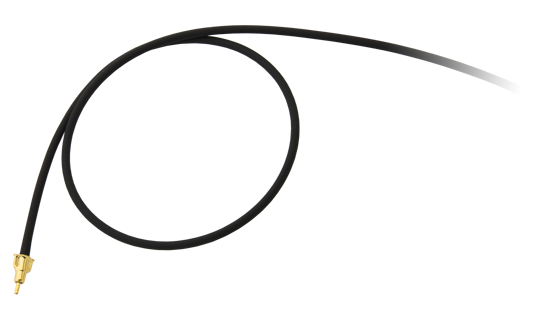
Coaxial cable
...more info- For STD-302Z and LMD-401, why should continuous Hi or Low input data be within 20 ms?
- How do I control the PLL on the STD-302Z / LMD-401?
- What is transparent interface?
- What is RSSI? And how to use it?
- What is 12dB SINAD?
- Signals similar to data seem to come out of the Data Out (DO) terminal, even when no signal is received. Why is this?
- Is it effective to use AF OUT output as a method for extending the communication range?
- What is the difference between DO and AF signal?
- Can I connect Circuit Design modules to Arduino or Raspberry Pi?
- I want to put the RF module in my enclosure? What do I need to be careful of?
- There is a problem with communication range. What is the problem? What should be checked?
- How should the antenna be handled?
- I need help in selecting a CPU to control my module?
- Can Circuit Design module communicate with a tablet?
- I'd like to use my own antenna on your module. Where can I find the suitable connector (e.g. SP060022)?
