- Overview
- Details
- Documents
- Dev. tools
- Accessories
- FAQ
- Sales Network
![]()
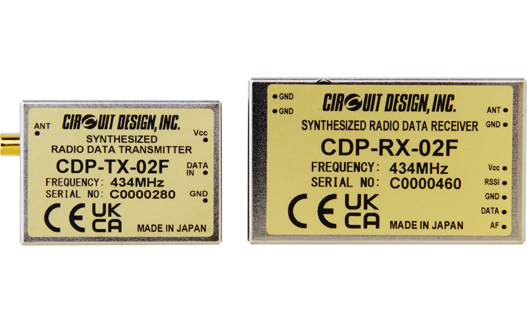
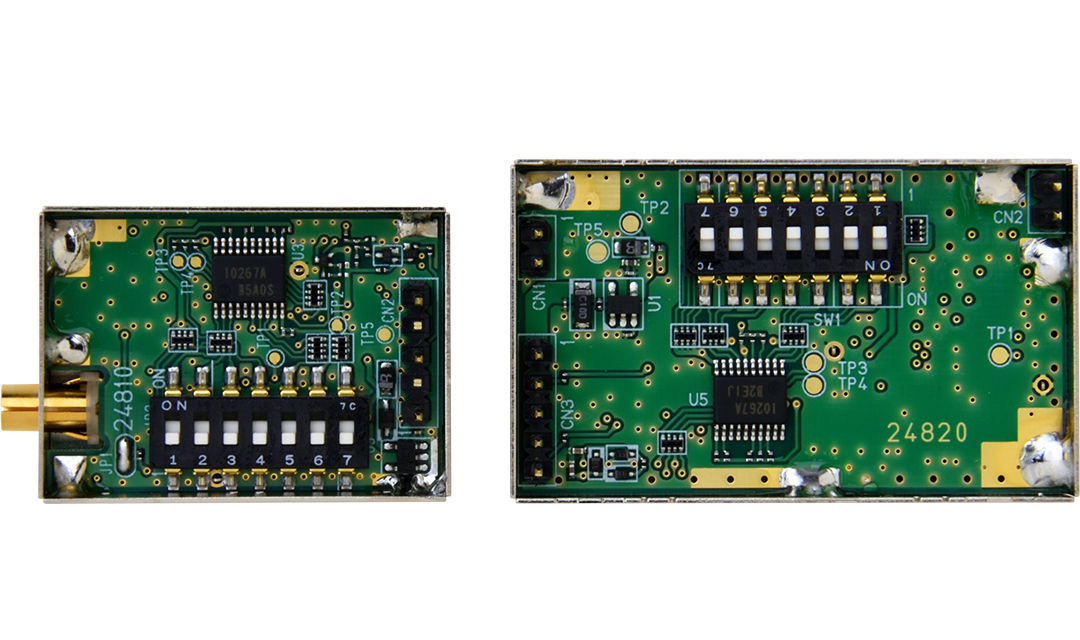
For the CDP-TX-02F, CDP-RX-02F, frequency setting is performed with the 7-bit switches.
They are suitable for various application fields such as wireless data communication, remote control, telemetry or wireless security systems. They are easy to use and integrate into application systems.
CDP-TX-02F and CDP-RX-02F are equipped with a frequency synthesizer system with micro controller. Available frequency ranges are from 128 preprogrammed channels. The compact size, low operating voltage and frequency selectability of the CDP-02F make it ideal for various applications where its interference rejection and propagation distance range is far better than similar RF modules based on wide band SAW-resonator frequency generators.
The CDP-RX-02F receiver has excellent blocking and adjacent channel selectivity.
Features
- 10 mW/1 mW RF power selectable
- Wide operating range (-20 to +60 degree C)
- Pre-programmed 128 ch
- Narrow band FM 12.5 kHz step
- PLL controlled VCO, data rate 4,800 bps
- Receiver sensitivity -120 dBm, 600 m operating range
- Receiver category 1.5
- RED compliant (EN 300 220)
Applications
- Industrial remote control
- Factory automation M2M
- Security systems
- Alarms
- Telemetry systems
Other products related to this product
Specifications
Common
| Parameter | Specification | Remarks |
|---|---|---|
| Applicable standard | RED compliant (EN 300 220) UK Radio Equipment Regulations 2017 |
|
| Communication form | One way | |
| Emission type | F1D | FSK narrow |
| Oscillation system | PLL controlled VCO | |
| Frequency | 433.1875 to 434.7750 MHz | |
| Number of RF channels | 128 channels | 12.5 kHz step |
| Channel spacing | 25 kHz | |
| RF bit rate | 300 to 4,800 bps | |
| Pulse width | Min. 208 us / Max. 20 ms | |
| Operating temperature range | -20 to +60 degree C | No dew condensation |
Transmitter Part
| Parameter | Specification | Remarks |
|---|---|---|
| Transmitter type | PLL synthesizer | |
| RF output power | 10 mW / 1 mW | |
| Data input | Digital L = GND, H = Vcc | |
| Deviation | +/-2.1 kHz | PN9 4,800 bps |
| Spurious emission | < -54 dBm (47 - 74 M, 87.5 - 118 M, 174 - 230 M, 470 - 862 MHz) < -36 dBm (Other frequencies < 1000 MHz) < -30 dBm (> 1000 MHz) |
|
| Adjacent channel power | < -37 dBm | |
| Supply voltage | 3.0 to 12 V DC | |
| Supply current | 43 mA typ. 33 mA typ. |
3 V/10 mW 3 V/1 mW |
| Dimensions | 36 x 26 x 10 mm | |
| Weight | 14 g | without antenna |
Receiver Part
| Parameter | Specification | Remarks |
|---|---|---|
| Receiver type | Double Superheterodyne PLL synthesizer | |
| Receiver category | 1.5 | |
| Receiver Sensitivity | -120 dBm typ. (12 dB SINAD) -120 dBm typ. (BER 1 %) |
|
| Adjacent channel selectivity | -50 dBm | +/-25 kHz |
| Blocking | -25 dBm | +/-2 MHz |
| -20 dBm | +/-10 MHz, 5% of center frequency | |
| Spurious radiation | < -60 dBm (< 1000 MHz) < -50 dBm (> 1000 MHz) |
|
| Data output | Digital (L = GND H = Vcc) | |
| Supply Voltage | 3.0 to 12 V DC | |
| Supply current | 30 mA typ. 33 mA typ. |
3 V 12 V |
| Dimensions | 50 x 30 x 9 mm | excluding protrusion |
| Weight | 20 g |
* For the specifications of the previous model (S/N C000xxxx), refer to the operation guide.
Specifications are subject to change without prior notice.
External View
CDP-TX-02F
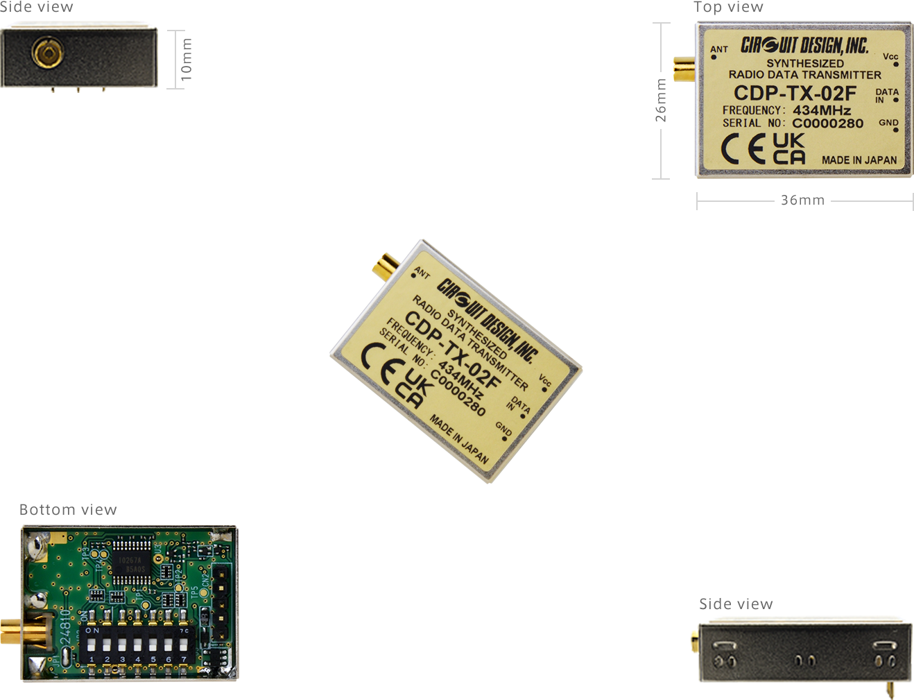
* Antenna, ANT-LEA-01-R, is included.
CDP-RX-02F
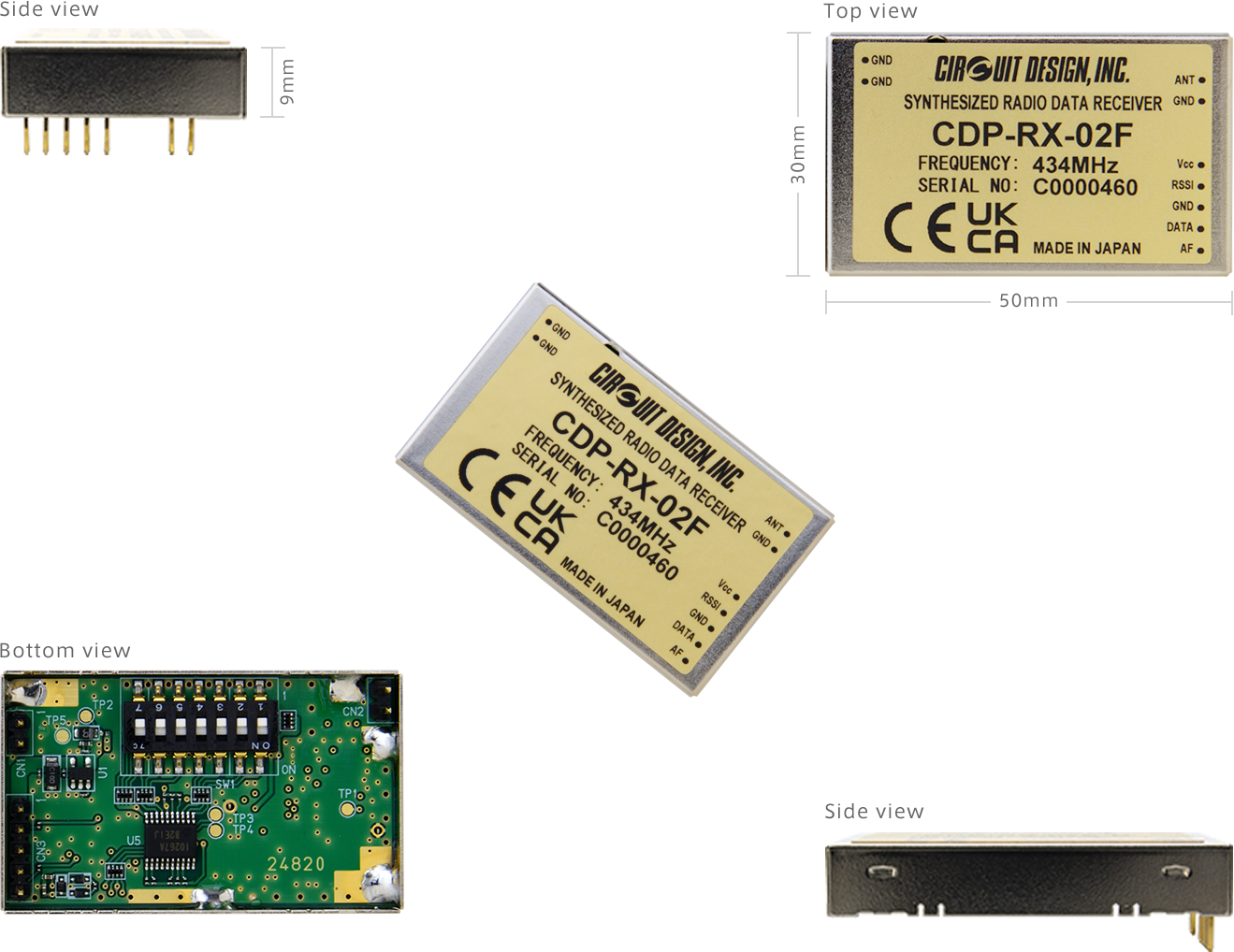
Operation Guides
| Version 1.1 (CDP-TX-02F 434 MHz) | |
|---|---|
| Version 1.0 (CDP-RX-02F 434 MHz) (S/N C000xxxx) | |
| Version 2.0 (CDP-RX-02F 434 MHz) (S/N C001xxxx) |
Application Notes
| Design guide for RF transmitter and receiver | |
|---|---|
| Notes for radio module control using a CPU |
Certifications
Parts Change Notice (PCN)
| PCN2391001 (Oct. 2023) | |
|---|---|
| PCN2302017 (Jan. 2023) | |
| PCN2102016 (Nov. 2021) |
Evaluation Tools: ECB-03, DCB-03
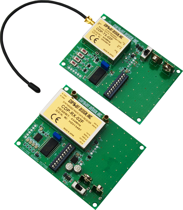
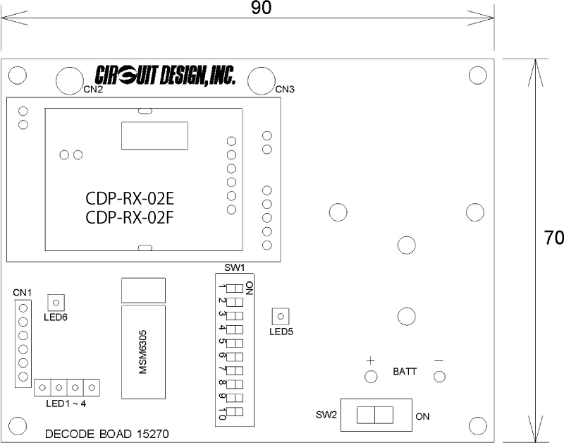
The test board ECB-03 (Encoder board) and DCB-03 (Decoder board) will save you time and effort for evaluating CDP-TX-02F, CDP-RX-02F modules. Communication range can be tested easily by checking the LEDs on the decoder board.
ECB-03 and DCB-03 do not include modules CDP-TX-02F, CDP-RX-02F. Please make sure to order them if needed.
Features of the Status Translation
- TX board: 8 inputs (optocoupler) & RX board: 8 outputs (photo MOS relays).
- Manual and automatic channel control
- Different transmission types (test mode, continuous mode, triggered mode)
- Learning and pairing mode (TX 1 : RX N or TX N : RX 1)
- 8 monitoring LEDs on the receiver board
- Data packets with CRC16 checksum
- Fail safe mode with max error count
- Calibrated to -116 dBm for automatic channel control
Features of the Development Set
- Fully programmable Atmel® ATMEGA324P over ISP port
- 32 kB internal flash and 2 kB EEPROM for original software
- 2 UART ports for CDP-02 and debugging/data transmission and reception
- 3 DIP switches for configuration
- Complete documented source code for status transmission
Features
- 4-push buttons and output LEDs.
- Encoder and decoder IC MSM6305 with the user selectable 1024 address codes.
External View
ECB-03
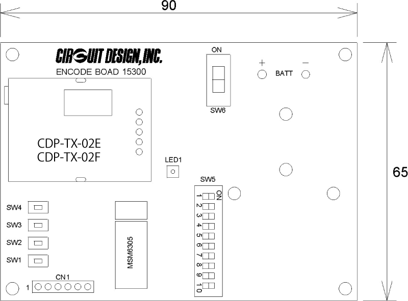
* Antenna, ANT-LEA-01-R, is included.
DCB-03
Accessories
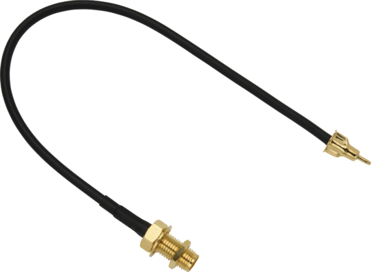
ANT-LEA-01-R
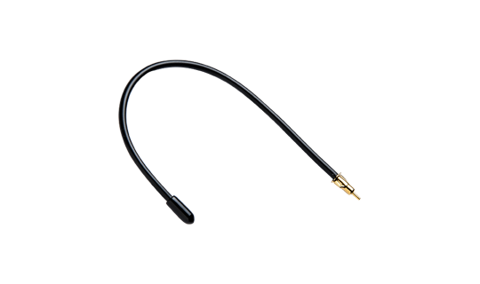
Lead antenna with plug
...more infoANT-RIG-01-R
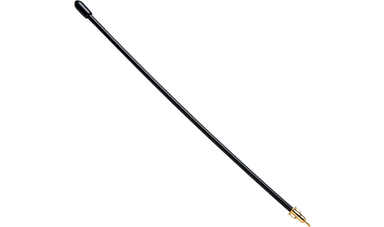
Rigid antenna with plug
...more infoANT-01-R
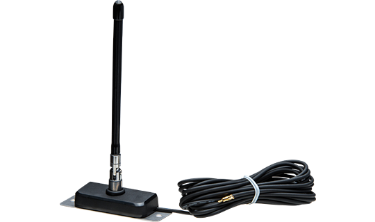
434MHz antenna with extension coaxial cable for the receiver
...more infoCBL-TMP-01-R
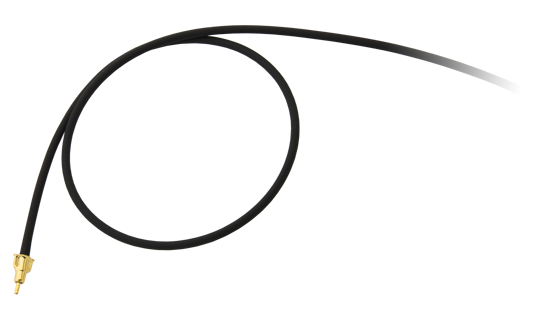
Coaxial cable
...more info- What are the differences between the CDP-TX/RX-02E and CDP-TX/RX-02F?
- What is transparent interface?
- What does 'Category 1 receiver' mean?
- What is RSSI? And how to use it?
- What is 12dB SINAD?
- Signals similar to data seem to come out of the Data Out (DO) terminal, even when no signal is received. Why is this?
- Is it effective to use AF OUT output as a method for extending the communication range?
- What is the difference between DO and AF signal?
- What are the frequencies of the intermediate frequency (IF) stages in the CDP-RX-02E/EP, CDP-RX-02F, CDP-RX-07M/MP, CDP-RX-05M-R?
- Can I connect Circuit Design modules to Arduino or Raspberry Pi?
- I want to put the RF module in my enclosure? What do I need to be careful of?
- There is a problem with communication range. What is the problem? What should be checked?
- How should the antenna be handled?
- I need help in selecting a CPU to control my module?
- Can Circuit Design module communicate with a tablet?
- I'd like to use my own antenna on your module. Where can I find the suitable connector (e.g. SP060022)?
