- Overview
- Details
- Documents
- Dev. tools
- Applications
- FAQ
- Sales Network
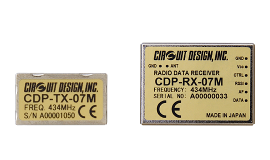
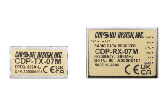
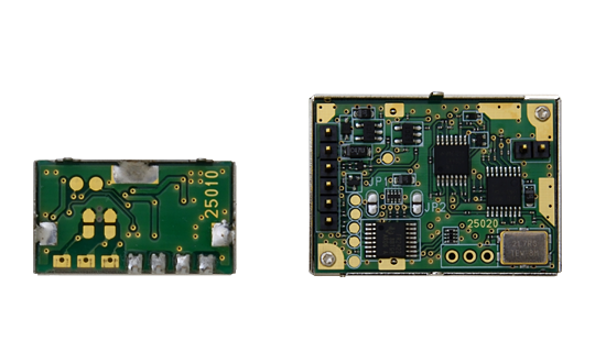
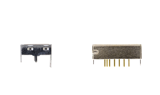
CDP-TX-07M / MP and CDP-RX-07M / MP are low power narrow band FSK transmitter and receiver modules, designed for industrial applications operating in 434 MHz and 869 MHz. The modules contain most of the components necessary for radio communication in compact cases. The operating RF channel can be selected from 4 preset frequency channels. The receiver is double-superheterodyne and equipped with a SAW filter, ensuring high sensitivity and very good selectivity for stable and long range communication.
The CDP-TX-07M, CDP-RX-07M is compatible with CDP-TX-05M-R and CDP-RX-05M-R
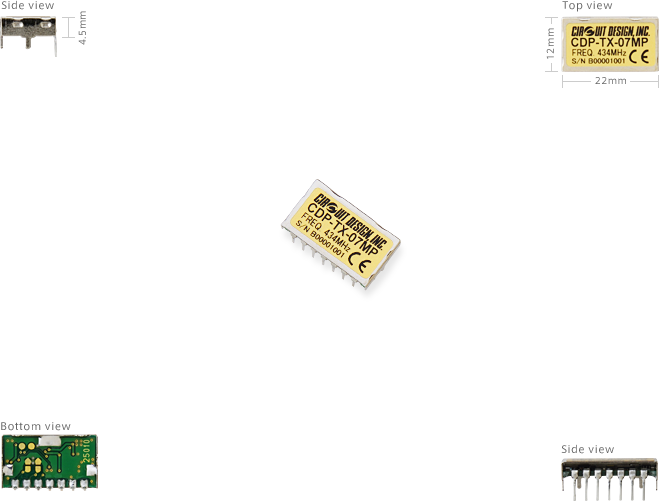
CDP-TX-07MP, CDP-RX-07MP has connection pins S1 and S2 allowing frequency setting to be performed externally.
| Model name | TX / RX | Ch setting |
|---|---|---|
| CDP-TX-07M | Transmitter | Jumper |
| CDP-RX-07M | Receiver | Jumper |
| CDP-TX-07MP | Transmitter | Pin connectors S1 and S2 |
| CDP-RX-07MP | Receiver | Pin connectors S1 and S2 |
Features
- RF output 10 mW (434 MHz), 5 mW (869 MHz)
- Wide operating temperature (-20 to +65 degree C)
- 4 preset channels* containing 4 frequencies
- PLL controlled VCO, data rate 100 to 4,800 bps FSK
- Compact size
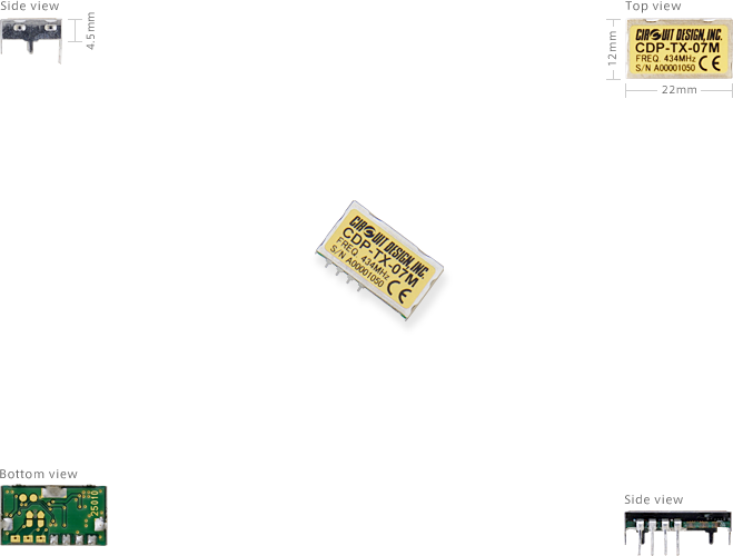
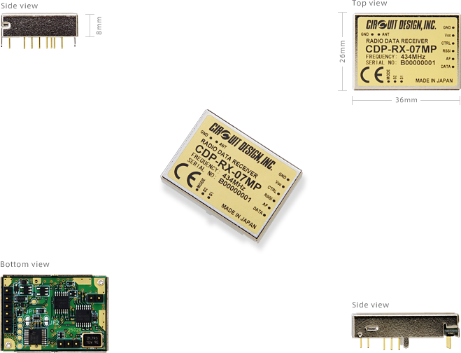
Transmitter 22 x 12 x 4.5 mm
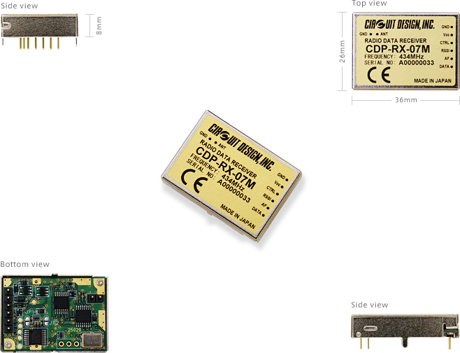
Receiver 36 x 26 x 8 mm - Receiver category 1 (434 MHz), category 1.5 (869 MHz)
- RED compliant (EN 300 220)
- Radio Equipment Regulations 2017 (UK)
* For the CDP-TX-07MP, CDP-RX-07MP 434 MHz and CDP-TX-07MP, CDP-RX-07MP 869 MHz, the user can reprogram each channel with a frequency selected from 67 frequencies in the 434 MHz band and 155 frequencies in the 869 MHz band respectively using a dedicated setting program.
Applications
- Remote control systems
- Security and alarm systems
- Telemetry and monitoring systems
- Tracking systems
Specifications
CDP-TX-07M/MP, CDP-RX-07M/MP 434 MHz
Common
| Parameter | Specification | Remarks |
|---|---|---|
| Applicable standard | RED compliant (EN 300 220) UK Radio Equipment Regulations 2017 |
CE marking and UKCA marking acquired |
| Communication method | One way | |
| Emission type | F1D | FSK narrow |
| Oscillation system | Crystal based PLL oscillation | |
| Number of channels | 4 channels * | |
| Frequency | 434.075 MHz 433.920 MHz 434.600 MHz 434.700 MHz |
|
| RF bit rate | 100 to 4,800 bps | |
| Pulse width | Min. 208 us / Max. 20 ms | |
| Operating temp. range | -20 to +65 degree C |
* Each of the 4 preset channels are reprogrammable using values chosen from a frequency table containing 67 values that consists of 433.920 MHz and values from 433.075 to 434.700 MHz with 25 kHz step. To reprogram the preset channels, a dedicated setting program is provided.
Transmitter Part
| Parameter | Specification | Remarks |
|---|---|---|
| Transmitter type | Crystal based PLL oscillation | |
| RF output power | 10 mW | |
| Data input | Digital L = GND, H = Vcc | |
| Deviation | +/-3.0 kHz | PN9 4,800 bps |
| Spurious emission | < -54 dBm (< 862 MHz) < -36 dBm (862 to 1000 MHz) < -30 dBm (> 1000 MHz) |
|
| Adjacent channel power | < -37 dBm | |
| Supply voltage | 2.2 to 5.5 V DC | |
| Supply current | 20 mA typ. | |
| I/O terminals | RF out, Gnd, Vcc, Data In, (JP1 / JP2) | CDP-TX-07M |
| RF out, Gnd, Vcc, Data In, Mode, S1, S2 | CDP-TX-07MP | |
| Dimension | 22 x 12 x 4.5 mm | |
| Weight | 2 g |
Receiver Part
| Parameter | Specification | Remarks |
|---|---|---|
| Oscillation system | Crystal based PLL oscillation | |
| Receiver category | 1 | |
| Receiver sensitivity | -120 dBm -115 dBm |
12 dB SINAD BER 0.1% |
| Adjacent channel selectivity | 45 dB | |
| Spurious radiations | < -60 dBm | |
| Data output | Digital L = GND, H = Vcc | |
| Supply voltage | 3.0 to 14 V DC | |
| Supply current | 23 mA typ. | 3 V |
| I/O terminals | Ant, Gnd, Vcc, Data out, AF out, RSSI out, Power Control, (JP1 / JP2) | CDP-RX-07M |
| Ant, Gnd, Vcc, Data out, AF out, RSSI out, Power Control, Mode, S1,S2 | CDP-RX-07MP | |
| Dimensions | 36 x 26 x 8 mm | |
| Weight | 13 g |
CDP-TX-07M/MP, CDP-RX-07M/MP 869 MHz
Common
| Parameter | Specification | Remarks |
|---|---|---|
| Applicable standard | RED compliant (EN 300 220) UK Radio Equipment Regulations 2017 |
CE marking and UKCA marking acquired |
| Communication method | One way | |
| Emission type | F1D | FSK narrow |
| Oscillation system | Crystal based PLL oscillation | |
| Number of channels | 4 channels * | |
| Frequency | 869.750 MHz 868.300 MHz 869.800 MHz 869.925 MHz |
|
| RF bit rate | 100 to 4,800 bps | |
| Pulse width | Min. 208 us / Max. 20 ms | |
| Operating temp. range | -20 to +65 degree C |
* Each of the 4 preset channels are reprogrammable using values chosen from a frequency table containing 155 values from 868.050 to 869.975 MHz with 12.5 kHz step. To reprogram the preset channels, a dedicated setting program is provided.
Transmitter Part
| Parameter | Specification | Remarks |
|---|---|---|
| Transmitter type | Crystal based PLL oscillation | |
| RF output power | 5 mW | |
| Data input | Digital L = GND, H = Vcc | |
| Deviation | +/-3.0 kHz | PN9 4,800 bps |
| Spurious emission | < -54 dBm (< 790 MHz) < -36 dBm (790 to 1000 MHz) < -30 dBm (> 1000 MHz) |
|
| Adjacent channel power | < -37 dBm | |
| Supply voltage | 2.2 to 5.5 V DC | |
| Supply current | 18 mA typ. | |
| I/O terminals | RF out, Gnd, Vcc, Data In, (JP1 / JP2) | CDP-TX-07M |
| RF out, Gnd, Vcc, Data In, Mode, S1, S2 | CDP-TX-07MP | |
| Dimension | 22 x 12 x 4.5 mm | |
| Weight | 2 g |
Receiver Part
| Parameter | Specification | Remarks |
|---|---|---|
| Oscillation system | Crystal based PLL oscillation | |
| Receiver category | 1.5 | |
| Receiver sensitivity | -115 dBm -110 dBm |
12 dB SINAD BER 0.1% |
| Adjacent channel selectivity | 45 dB | |
| Spurious radiations | < -60 dBm | |
| Data output | Digital L = GND, H = Vcc | |
| Supply voltage | 3.0 to 14 V DC | |
| Supply current | 23 mA typ. | 3 V |
| I/O terminals | Ant, Gnd, Vcc, Data out, AF out, RSSI out, Power Control, (JP1 / JP2) | CDP-RX-07M |
| Ant, Gnd, Vcc, Data out, AF out, RSSI out, Power Control, Mode, S1,S2 | CDP-RX-07MP | |
| Dimensions | 36 x 26 x 8 mm | |
| Weight | 13 g |
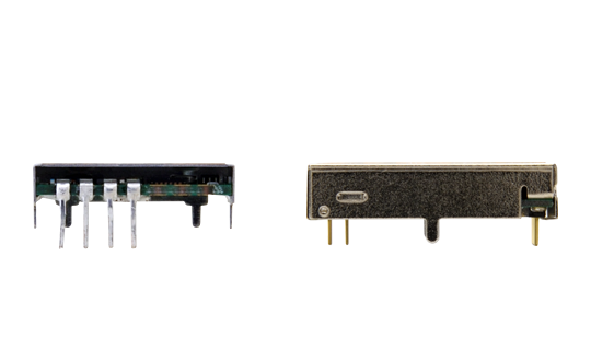
External View
CDP-TX-07M
(The images shown also apply to the CDP-TX-07M 869 MHz)
CDP-RX-07M
(The images shown also apply to the CDP-RX-07M 869 MHz)
CDP-TX-07MP
(The images shown also apply to the CDP-TX-07MP 869 MHz)
CDP-RX-07MP
(The images shown also apply to the CDP-RX-07MP 869 MHz)
Operation Guides
| Version 2.1 (CDP-TX-07M/MP 434 MHz) | |
|---|---|
| Version 2.1 (CDP-RX-07M/MP 434 MHz) | |
| Version 1.0 (CDP-TX-07M/MP 869 MHz) | |
| Version 1.0 (CDP-RX-07M/MP 869 MHz) |
Application Notes
Certifications
Parts Change Notice (PCN)
| PCN2391001 (Oct. 2023) | |
|---|---|
| PCN2206002 (Apr. 2022) | |
| PCN2106001 (Sept. 2021) |
Evaluation Tools: TB-CDP-TX-04S, TB-CDP-RX-03AS
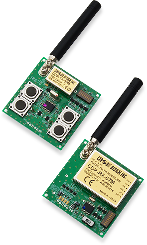
The test board will save you time and effort for evaluating CDP-TX-07M and CDP-RX-07M modules. Communication range can be tested easily by checking the LEDs on the decoder board TB-CDP-RX-03AS.
TB-CDP-TX-04S and TB-CDP-RX-03AS do not include modules CDP-TX-07M and CDP-RX-07M. Please make sure to order them if needed. The boards are common for CDP-TX-05M-R / RX-05M-R models. Also the testboard cannot be used for CDP-TX-07MP and CDP-RX-07MP.
Features
- 4-push buttons and output LEDs
- 8-bit ID dip switch
![[ Video ] [ CDP-TX-07MP, CDP-RX-07MP ] - Showing how to customise the channel table in the transmitter and receiver CDP-TX-07MP, CDP-RX-07MP 869 MHz using Windows setting program.](https://www.cdt21.com/wp/wp-content/uploads/2023/01/869mhz-cdp07mp-how-to-reprogram-the-channel-table.png)
[ Video ] [ CDP-TX-07MP, CDP-RX-07MP ] - Showing how to customise the channel table in the transmitter and receiver CDP-TX-07MP, CDP-RX-07MP 869 MHz using Windows setting program.
![[ Video ] [ CDP-TX-07MP, CDP-RX-07MP ] - Showing how to customise the channel table in the transmitter and receiver CDP-TX-07MP, CDP-RX-07MP 434 MHz using Windows setting program.](https://www.cdt21.com/wp/wp-content/uploads/2023/01/cdp07mp_reprogramming-the-channel-table.png)
[ Video ] [ CDP-TX-07MP, CDP-RX-07MP ] - Showing how to customise the channel table in the transmitter and receiver CDP-TX-07MP, CDP-RX-07MP 434 MHz using Windows setting program.
- What is difference between M and MP?
- What is transparent interface?
- What does 'Category 1 receiver' mean?
- What is RSSI? And how to use it?
- What is 12dB SINAD?
- Signals similar to data seem to come out of the Data Out (DO) terminal, even when no signal is received. Why is this?
- Is it effective to use AF OUT output as a method for extending the communication range?
- What is the difference between DO and AF signal?
- What are the frequencies of the intermediate frequency (IF) stages in the CDP-RX-02E/EP, CDP-RX-02F, CDP-RX-07M/MP, CDP-RX-05M-R?
- Can I connect Circuit Design modules to Arduino or Raspberry Pi?
- I want to put the RF module in my enclosure? What do I need to be careful of?
- There is a problem with communication range. What is the problem? What should be checked?
- How should the antenna be handled?
- I need help in selecting a CPU to control my module?
- Can Circuit Design module communicate with a tablet?
- I'd like to use my own antenna on your module. Where can I find the suitable connector (e.g. SP060022)?
