- Overview
- Details
- Documents
- Dev. tools
- Accessories
- Applications
- FAQ
- Sales Network
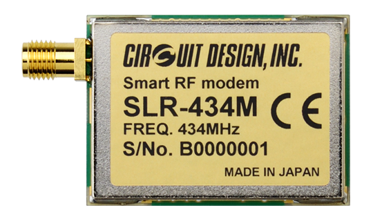
The SLR-434M smart modem is a compact, easy to use embedded radio modem operating in the 434 MHz ISM band. It allows conventional FSK mode communication and also communication using LoRa® mode providing long range at lower bit rate.
With high receiving sensitivity, it is possible to transmit up to a few km or more with line of sight using low RF output power.
By connecting to an external CPU or PC with UART interface, the user can send data or design simple control systems using Circuit Design's dedicated command protocol for industrial application. It is also possible to process up to 8 switching signals.
Applications include data transmission, telemetry and telecontrol.
* Under certain conditions when LoRa modulation is used in conjunction with low data rate, higher sensitivity is achieved and longer range becomes possible. When used in conventional FSK mode, up to 600 m (LOS) range should be expected.
The SLR-434M contains a Semtech's LoRa® wireless RFIC.
The LoRa® Mark and LoRa Logo are trademarks of Semtech Corporation.
Features
- RED compliant (EN 300 220)
- Extremely long range operation achieved by LoRa® mode.
- Switchable between FSK mode and LoRa® mode
- UART interface (COM port, RS232)
- Simple command protocol for development of user program.
- Transmission of up to 8 switching signals using IO terminals.
- Compact size
- Low voltage and current consumption
- Higher resistance to urban noise, enabling long range operation compared to conventional FSK
- 429 MHz version available (Japan)
Applications
- Data transmission in buildings, air conditioning control
- Debris flow monitoring at mudslide control dams
- River water level / dam monitoring
- Greenhouse temperature / humidity monitoring and control
- Sensor data transmission from underground or manhole
- Monitoring of tunnels and bridge condition
- Landslide warning
Other products related to this product
Specifications
General
| Parameter | Specification | Remarks |
|---|---|---|
| Standard | EN 300 220 | |
| Emission type | F1D | |
| RF output power | < 10 mW | Nominal, Contact (50 Ω), SMA |
| Communication method | Simplex or half duplex | |
| RF bit rate | 15 to 245 bps (LoRa® mode) 4800 bps (FSK mode) |
Actual speed with LoRa mode depends on spreading factor |
| Frequency range | 433.0750 to 434.7750 MHz | |
| Number of channels | 137 | Channel step 12.5 kHz |
| Receiver sensitivity | < -133 dBm (LoRa mode 128chip) < -115 dBm (FSK mode) |
|
| Supply voltage | 3.3 to 5.5 V | 3.5 to 5.0 V recommended |
| Supply current | 29 mA typ. (TX) 17 mA typ. (RX) |
5 V |
| External dimensions (WxDxH) |
40 × 29 × 6.2 mm | Not including the antenna connector |
| Modulation | 2-FSK or LoRa | Selectable using command |
| Number of I/O | 8 |
The LoRa® Mark and LoRa Logo are trademarks of Semtech Corporation.
UART Interface
| Parameter | Specification | Remarks |
|---|---|---|
| Communication method | Serial communication | RS232C format |
| Synchronization | Asynchronous / UART | |
| UART bitrate | 19,200 bps | |
| Flow control | Hardware: RTS/CTS pin Software: Xon/Xoff not used |
|
| Other parameters | Data length 8 bits, no parity, 1 (or 2) stop bits |
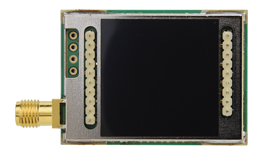
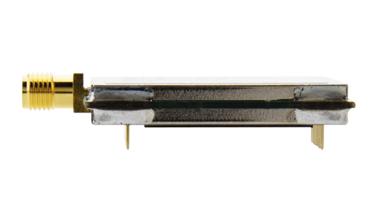
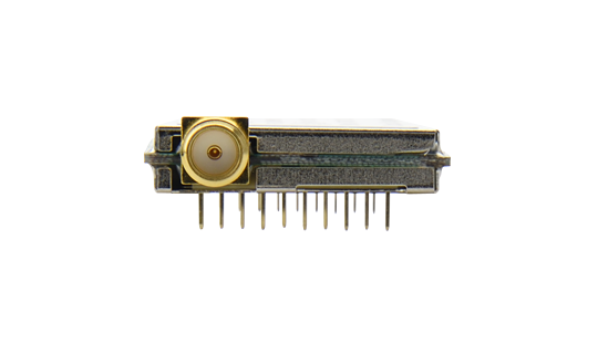
External View
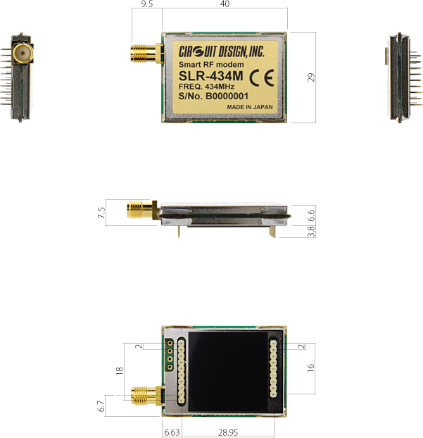
Operation Guides
| Embedded low power radio modem (Version 3.0) | |
|---|---|
| Serial communication (Version 2.0) | |
| Command input and response timing (Version 1.0) | |
| Evaluation Program Manual (Version 1.1) |
Certifications
| DoC for CE (SLR-434M) |
|---|
Parts Change Notice (PCN)
| PCN2391001 (Oct. 2023) | |
|---|---|
| PCN2241001 (March 2022) |
Test Board: TB-SLR-RS2
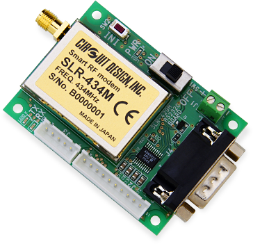
The TB-SLR-RS2 is an RS232 interface board for testing SLR-434M module. It can connect to the COM port of PC or PLC through the D-Sub-9 pin connector. The board is equipped with transmit, receive LED, power supply terminal, main switch and interface to sub boards. The module can be used with coax extension cable to allow optimum placement of the antenna according to the environment. Click here for more details.
This testboard does not include the modem SLR-434M. Please order if necessary.
Features
- Connection to PC COM port for data communication and module control
- Using RS232 cable, extension to tens of meters possible.
- Evaluation program available
- Interface to sub-boards for switching operation.
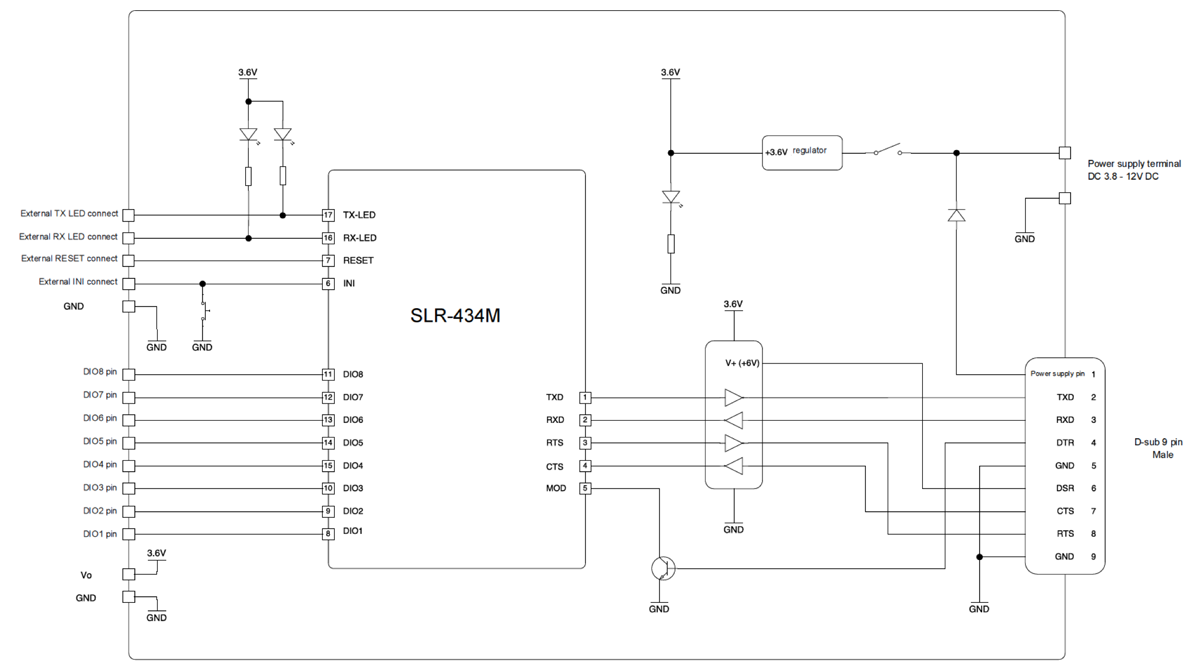
External View
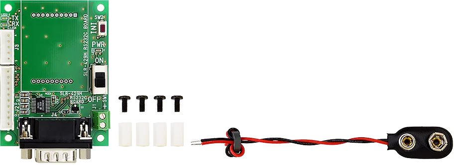
Screw x 4
Spacer x 4
Battery clip x 1
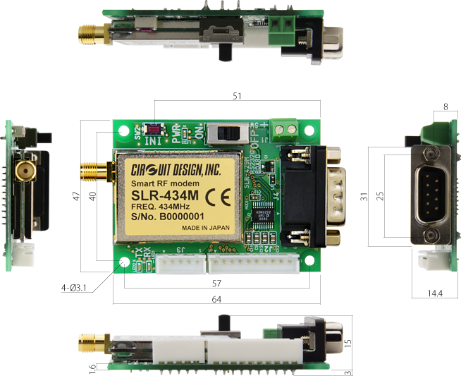
Connection to PC

For other connection methods, please refer to the TB-SLR-RS2 operation guide.
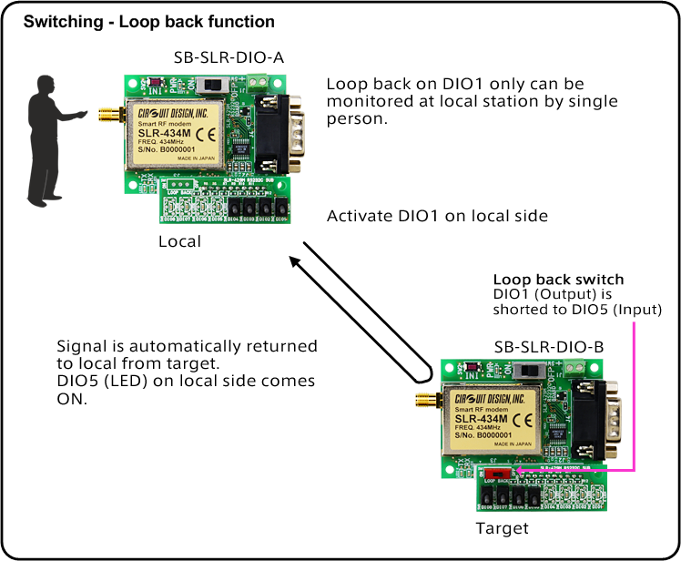
Switching Operation
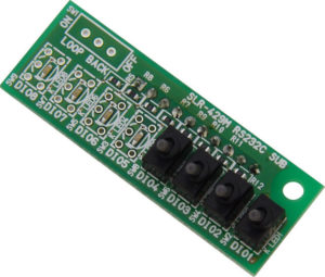
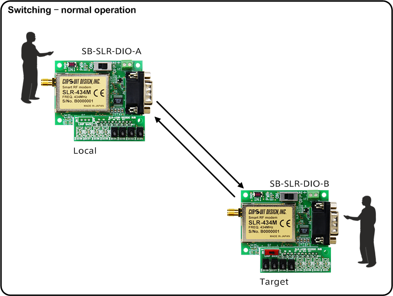
Using the interface on the TB-SLR-RS2, sub boards can be attached to allow switching and loop back tests to be performed.
SB-SLR-DIO-A
SB-SLR-DIO-B
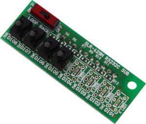
Note: sub boards SB-SLR-DIO-A and SB-SLR-DIO-B are required to perform the switching and loop back function and are not included. Please ensure you order them if necessary.
Accessories
CBL-SMA-SMARE2-50
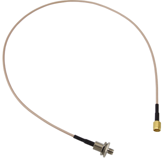
SMA - RPSMA conversion cable
...more infoCBL-SMA-SMA-50
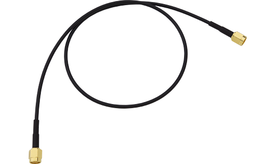
SMA - SMA conversion cable
...more info![[ Video ] [ SLR-434M ] - Introducing the low power long range radio modem.](https://www.cdt21.com/wp/wp-content/uploads/2023/01/low-power-long-range-radio-modem.png)
[ Video ] [ SLR-434M ] - Introducing the low power long range radio modem.
![[ Video ] [ SLR-434M ] - Demonstrating the embedded radio modem SLR-434M: Development Kit](https://www.cdt21.com/wp/wp-content/uploads/2023/01/slr-434m_development-kit.png)
[ Video ] [ SLR-434M ] - Demonstrating the embedded radio modem SLR-434M: Development Kit
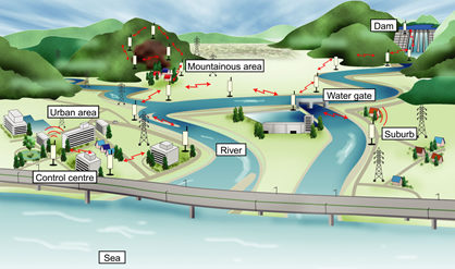
SLR-434M Application examples
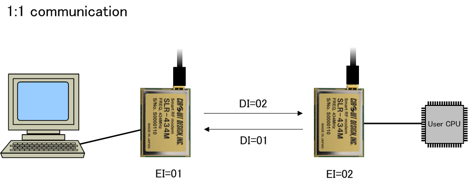
SLR-434M System examples
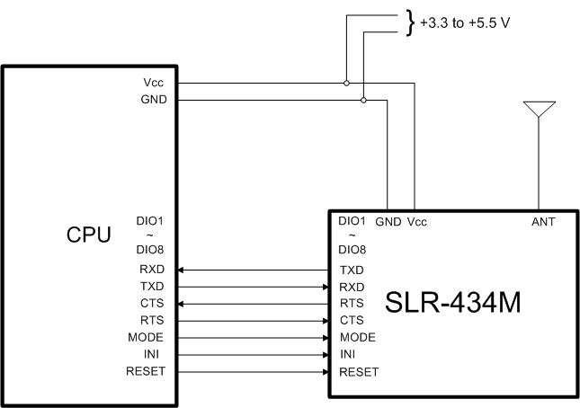
SLR-434M Connection examples
![[ Video ] [ SLR-434M ] - Introducing the evaluation software for the low power RF modem, SLR-434M](https://www.cdt21.com/wp/wp-content/uploads/Fukui/slr434m_introducing-the-evaluation-program-for-the-low-power-long-range-radio-modem.png)
[ Video ] [ SLR-434M ] - Introducing the evaluation software for the low power RF modem, SLR-434M
![[ Video ] [ SLR-434M ] - Demonstrating serial data communication with the low power RF modem SLR-434M.](https://www.cdt21.com/wp/wp-content/uploads/2023/01/slr434m_data-communication-using-evaluation-software-program-and-test-board.png)
[ Video ] [ SLR-434M ] - Demonstrating serial data communication with the low power RF modem SLR-434M.
- What are RS232C straight and null modem cables and which one do I use for the TB-SLR-RS2?
- What is the LoRa® used in the SLR-434M?
- What are the DIO terminals on the SLR-434M?
- What is the interface to the SLR-434M?
- What is the Air monitor feature?
- What is the loop back test for the SLR-434M?
- Can I connect Circuit Design modules to Arduino or Raspberry Pi?
- I want to put the RF module in my enclosure? What do I need to be careful of?
- There is a problem with communication range. What is the problem? What should be checked?
- How should the antenna be handled?
- I need help in selecting a CPU to control my module?
- Can Circuit Design module communicate with a tablet?
