- Overview
- Details
- Documents
- Dev. tools
- Accessories
- FAQ
- Sales Network
![]()
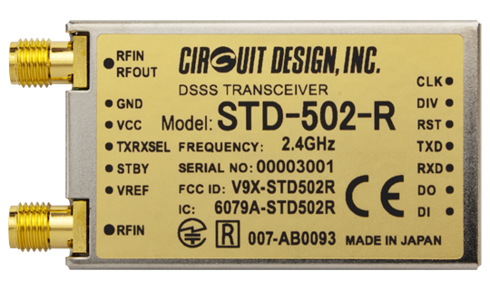
The STD-502-R 2.4 GHz transceiver uses direct sequence spread spectrum (DSSS) modulation and a true diversity circuit, enabling reliable communications even in the congested 2.4 GHz band.
The STD-502-R complies with the European ETSI EN300440, U.S. FCC Part 15.247, Canadian ISED RSS-210 standards and Japanese ARIB STD-T66, making it ready for the global market.
Low power consumption and battery operation give the STD-502-R the performance demanded for applications where long range and reliability are required.
The transceiver uses a transparent data interface to enable users to communicate using their own protocols.
The modules can be set easily via the UART interface using dedicated commands.
Circuit Design developed an onboard ASIC containing SS correlator (a key part of spread spectrum communications) instead of relying upon conventional RFICs. This ensures long term supply for industrial applications.
Features
- CE, FCC, ISED and ARIB conformity certification
- Uses direct sequence spread spectrum (DSSS) modulation
- A true diversity receiver containing two built-in receiver circuits
- Module settings using dedicated commands
- Data communication using transparent interface
- Low power operation
- 77 channels
- Communication LOS: 300 m
Applications
- Industrial telecontrol
- Telemetry Systems
Specifications
Common
| Parameter | Specification | Remarks |
|---|---|---|
| Applicable standard | EN 300 440 FCC part 15.247 ARIB STD-T66 ISED RSS-210 |
|
| Communication method | Simplex | |
| Transmission method | Direct sequence spread spectrum | |
| Emission type | F1D | FSK |
| Frequency | 2402.5 to 2478.5 MHz | |
| Number of RF channels | 77 | |
| Channel spacing | 1 MHz | |
| Data bit rate | 9.6 k / 19.2 kbps | |
| Chip rate | 144 k / 288 kcps | |
| RF connectors | RP-SMA x 2 | Nominal 50 ohm |
| Spreading code | 15 Chips | M-sequence ( 111101010001100 ) |
| Operating temperature range |
-20 to +65 degree C | No dew condensation |
| Supply voltage | 3.3 to 5.5 V DC | |
| Supply current | TX: 55 mA typ. RX: 65 mA typ. |
|
| Dimension | 50 x 30 x 9 mm | Not including connectors |
| Weight | 24g |
Transmitter Part
| Parameter | Specification | Remarks |
|---|---|---|
| RF output power | < 10 mW | e.i.r.p. |
| TX data input | Digital L = 0 to 0.25 H = Vref - 0.4 to Vref |
Receiver Part
| Parameter | Specification | Remarks |
|---|---|---|
| RF Input level | < -13 dBm | |
| Receiver sensitivity | -93 dBm | 19.2 kbps, BER 0.1% |
| RX data output | Digital L = GND, H = Vref |
Interface
| Parameter | Specification | Remarks |
|---|---|---|
| RF Data Interface | ||
| Port | DO / DI / CLK | |
| Data bit rate | 9.6 k / 19.2 kbps | Sync: CLK terminal |
| Command interface | ||
| Port | TXD / RXD | |
| Interface | UART communication (RS232C format) | |
| Communication method | Asynchronous | |
| UART bit rate | 19.2 k / 38.4 k / 57.6 kbps | |
| Flow control | None | |
| Other parameters | Data length: 8 bits / Parity (None) / Stop bits 2 |
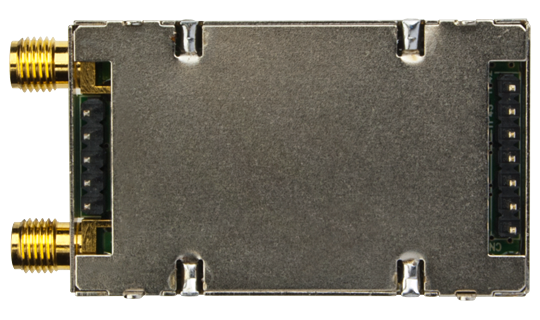
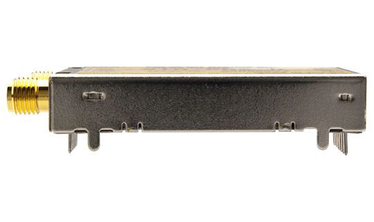
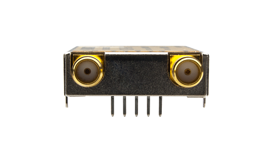
External View
STD-502-R
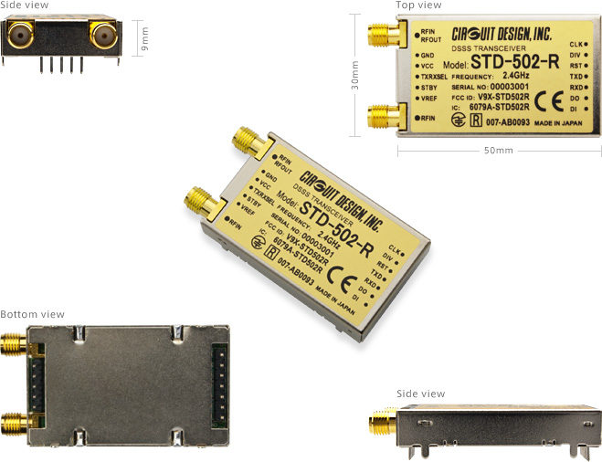
Operation Guide
| Version 2.2 |
|---|
Certifications
| DoC for CE (STD-502-R) | |
|---|---|
| FCC (STD-502-R) | |
| ISED (STD-502-R) |
Evaluation Tools: TB-STD502
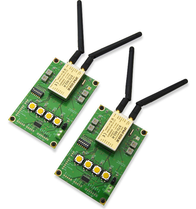
The TB-STD502 evaluation board allows you to evaluate our STD-502 module and perform range, data packet and switching signal transmission tests. Onboard LEDs, CH switch, ID switch and push buttons allow you to easily make switching signal tests and packet tests with packet error indication.
The boards do not include both modules STD-502. Please order them separately if needed.
Features
- 4-push buttons and output LEDs.
- Channel and ID switches
- External input/output pins
- Receiving antenna LED indicatorPacket test function
- Transmission mode DIP switch setting
External View
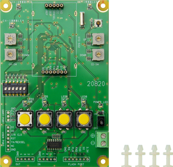
Spacer x 4
Accessories
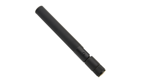
ANT-2G4W1R-R
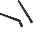
STD-502-R Antenna
...more info- What is the difference between the STD-502-R and STD-503?
- What is the benefit of DSSS?
- What exactly is the diversity receiver feature in the STD-502-R and STD-503?
- I want to put the RF module in my enclosure? What do I need to be careful of?
- There is a problem with communication range. What is the problem? What should be checked?
- How should the antenna be handled?
- I need help in selecting a CPU to control my module?
- Can Circuit Design module communicate with a tablet?
